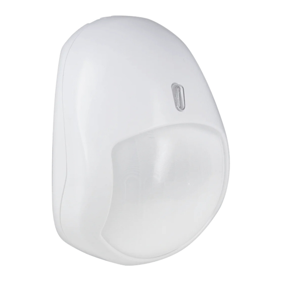
bolid S2000-IK Instruction Manual - Page 2
Browse online or download pdf Instruction Manual for Security Sensors bolid S2000-IK. bolid S2000-IK 4 pages. Addressable volumetric pir motion detector
Also for bolid S2000-IK: Operating And Installation Manual (3 pages)

INSTALLING THE DETECTOR
1. Using a screwdriver remove the cover screw at the bottom of the
detector (see Figure 2) and separate the detector cover.
2. Using a screwdriver remove the PCB screw (see Figure 2) and lift
the PCB out of the detector base.
3. Drill out the required mount and wiring holes in the base (see
Figure 2).
4. Having selected the mounting location, mark the positions of the
fixing holes taking into account mounting holes in the base, and drill
holes at the marked places
5. Slide the wire into the wire holes leaving some centimeters for
connecting wires to the terminal blocks
6. Finally, replace the PCB and tighten the PCB screw
WIRING
Figure 3a shows the way to connect detector's PL
contacts which are situated at the top of its PCB
to the relevant contacts of the S2000-KDL.
Figure
3b
shows
the
connecting
the
detector
addressable loop of the S2000-KDL controller
which is in turns connected to the network
controller and the power supply.
a) Connection Terminals
PROGRAMMING
The S2000-IK rev.04 to operate properly within two-wire addressable polling loop of the S2000-KDL controller, it must be
assigned to a unique number 1 to 127 within the loop – the address which is stored in the S2000-IK rev.04 non-volatile
memory (EEPROM). This address provides identifying the detector by the S2000-KDL controller. Moreover, the
monitoring strategy must be defined which will be used by the S2000-KDL controller while processing signals received
from the S2000-IK rev.04.
Programming the S2000-IK Rev.04 Address within the S2000-KDL Addressable Loop
An S2000-IK rev.04 is supplied with the default address of 127. This address value can be changed using either
S2000(M) console tools or PC tools such as UProg Configuration Tool.
In order to program the unique S2000-IK rev.04 loop address, connect it to a S2000-KDL controller which is in turns
connected to a network controller (an S2000(M) console or PC under UProg software). Then send one of the following
commands to the S2000-KDL controller (for getting more information see the relevant User's Manual):
Change the Device Address
wiring
diagram
for
to
the
multiplex
Figure 3 Connecting the Detector
Use the Change Device Address command specifying the old detector address and the
new detector address as the parameters (see more information in the referred
Manuals). The network controller will display the messages about disconnecting the
device with the old address and then detecting the device with newly programmed
address.
S2000-KDL
3
4
S2000-IK
1
+PL
5
− − − − PL
2
6
1
2
b) Detector's Wiring Diagram
Figure 2: Detector Base
S2000(M)
RS-485A
1
RS-485B
2
1
2
+PL
− − − − PL
GND
+U
Power Supply
1
2
A
B
+12 V
GND
+12 V
GND
