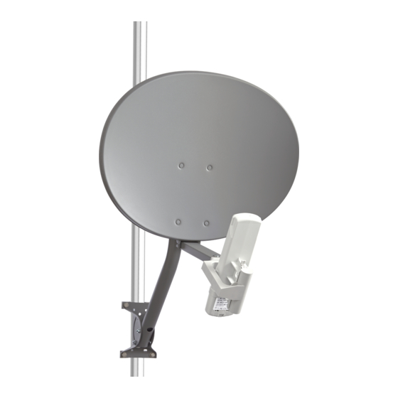
CANOPY 27 RD Assembly And Installation - Page 2
Browse online or download pdf Assembly And Installation for Antenna CANOPY 27 RD. CANOPY 27 RD 2 pages. Reflector

5
ANTENNA
REFLECTOR
Place Feed Tube on a solid surface or
table. The Reflector end of the Feed Tube
has a large hole on the bottom side. Align
bolt holes and press Reflector Socket
completely onto Feed Tube as shown.
7
Slide assembled
radio and mount
into feed tube as
shown.
9
Install Mast on tower or building. For Backhaul,use provided U-Bolts. For Subscriber Module, use locally
approved fasteners (lag bolts, screws, etc.) depending on installation. Adjust Mast to be vertical and plumb.
Tighten all hardware securely. Connect Ground Screw to Earth Ground using heavy guage (10AWG) copper
wire. Refer to local or national electrical regulations for exact specifications.
BACKHAUL MOUNT
V-BRACKET
UP TO
3.25" O.D.
PIPE (8.0cm O.D.)
U BOLT
6
Assemble the Feed Tube to the Reflector as
shown with 1/4" Flange Nut, .81" Spacer,
Flat Washer and 1-1/2" Hex Bolt. Tighten
hardware securely.
FEED TUBE
8
Secure Radio Mount to Feed Tube with #10 x 1-1/4"
Carriage Bolt and #10 Nut. Tighten Nut to snug the
bottom of the tube up to the Mount.
#10 x 1-1/4"
CARRIAGE
BOLT
#10 NUT
SUBSCRIBER MOUNT
10 AWG
GROUND
WIRE
MAST
GREEN
GROUND
SCREW
ALTERNATE
GROUND
SCREW HOLE
STAR
NUT
LOCALLY APPROVED FASTENERS
10
1/4" HEX
AZ/EL
FLANGE NUT
MOUNT
CLAMP
AZ/EL MOUNT
SPACER
FLAT
MAST
WASHER
Loosen bolts on AZ/EL Mount Clamp. Slide AZ/EL
1-1/2"
Mount with preassembed Reflector over mast.
HEX BOLT
Loosely tighten AZ/EL Mount Clamp.
12
ELEVATION
The Elevation is set by rotating the Reflector vertically while the Elevation Adjustment Hardware is loose.
An elevation scale is located on the side of the AZ/EL Mount. As the Reflector is adjusted, the elevation
scale depicts the elevation angle. Once the elevation is determined, tighten BOTH Elevation Ajustment Nuts
to secure the required angle.
11
To adjust azimuth, move Reflector from side to side
while AZ/EL Clamp Hardware is loose. Once azimuth
is determined, tighten (2) AZ/EL Clamp Nuts securely.
AZ/EL
CLAMP
NUTS
Read indicated elevation at this
edge of plate. The Beam from
the Reflector will be horizontal
when the Mast is vertical and
the plate is set at 4.5 degrees
up-elevation as shown.
REFLECTOR
ELEVATION
ADJUSTMENT
NUT (ONE ON
EACH SIDE)
