Cansec Zodiac FR100 Installation Manual - Page 6
Browse online or download pdf Installation Manual for IP Access Controllers Cansec Zodiac FR100. Cansec Zodiac FR100 15 pages.

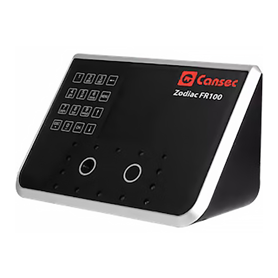
Reader Layout
Terminal Block (Pin 6 – 10)
Pin 6 & 7 are internally connected. 12VDC
input to pin 6 will also supply 12VDC to pin 7
and vice versa.
Pin 8 & 9 are internally connected. Both pins
have the same ground.
Those extra pins are provided for wiring
convenience, e.g. use pin 6 & 8 to power the
reader and pin 7 & 9 to power other device
TM
Zodiac FR100
Installation Manual
1. 3.5 inch TFT Color LCD
2. Navigational keys
3. Cansec label
4. Right camera
5. Left camera
6. LED
7. Confirmation key
8. Escape/Cancel key
9. Alphanumeric key
10. Backspace key
11. Menu key
12. USB port
13. Mounting plate screw
14. Reset button
15. RJ-45 jack
16. 12VDC input jack
17. Terminal blocks
18. SD card slot
19. Mounting plate
20. Speaker
21. Tamper switch
June 2014 • Rev. 1.2
Page 6 of 15
