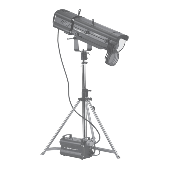
CANTO 2000 Instruction Manual - Page 5
Browse online or download pdf Instruction Manual for Spotlight CANTO 2000. CANTO 2000 11 pages. Follow spotlight metal halide and tungsten-halogen

1. RECEIVING
Upon opening the packaging, locate and identify the following:
Spotlight
a. Followspot
b. Iris (blackout iris diaphragm if specifically ordered; not available for Canto 2000)
c. Truss pin/spigot (1.11" diameter) with 12mm self-locking nut and plain washer
d. Instruction manual
Power Supply (only for Canto 575, Canto 700 and Canto 1200 metal halide)
a. 110/120 Volt, 50/60 Hz. ballast
2. MOUNTING THE SPIGOT/TRUSS PIN
a. Make sure the tripod you are going to use features a 1.1" (28mm) diameter top aperture.
b. Remove the nut and the washer from the spigot.
c. Insert the spigot in the central hole of the yoke of the followspot from beneath the yoke.
d. Add the plain washer and the self-locking nut and tighten the nut with a suitable wrench.
e. Mount the followspot on the tripod or truss. Make sure the structure to which you are fixing the
spotlight to is rated for the product load:
3. MOUNTING THE COLOR BOOMERANG (optional accessory, Part No. 20105006)
a. Remove the color frame from the front of the followspot optical system.
b. At the front of the followspot, remove the (2) cross-head self-tapping screws from one of the two
front color runners. Reposition the two screws in their original holes and tighten them.
c. Repeat with the second color runner.
d. Take the (3) supplied 4mm socket head screws and position each one of them, only halfway through,
in each one of the 4mm-threaded Avdel brass inserts on the front plate of the followspot optical
system housing.
e. Mount color filters on the boomerang arms. See relevant instructions supplied with the boomerang.
f. Position the boomerang unit on the front plate of the followspot, making sure that the color levers are
positioned on the right-hand side of the followspot (when viewed from behind). Hang it using the
keyhole openings in the boomerang frame onto the previously positioned socket head screws.
g. Release the color filters of the boomerang to allow access to the (3) screws and tighten them.
h. Ensure the boomerang unit is secure, and all three screws are tight.
NOTE: Do not discard the removed color runners and color frame, as they will be needed if the follow
spot is returned to its original, standard configuration.
Canto 575, 700, & 1200:
Canto 1000, 2000:
37 lb. (16.4 kg)
34 lb. (15.1 kg)
3
