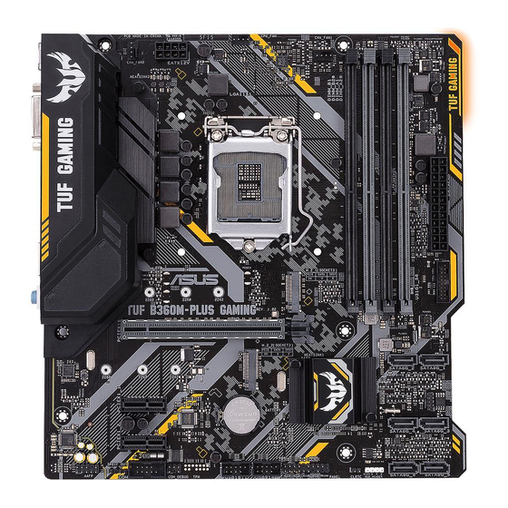
Asus TUF B360M-PLUS GAMING/BR Manual - Page 13
Browse online or download pdf Manual for Motherboard Asus TUF B360M-PLUS GAMING/BR. Asus TUF B360M-PLUS GAMING/BR 28 pages.
Also for Asus TUF B360M-PLUS GAMING/BR: Quick Start Manual (2 pages)

Digital audio connector (4-1 pin SPDIF_OUT)
Connect the S/PDIF Out module cable to this connector, then
install the module to a slot opening at the back of the system
chassis.
Front panel audio connector (10-1 pin AAFP)
This connector is for a chassis-mounted front panel audio I/O module that supports
either HD Audio or legacy AC`97 audio standard. Connect one end of the front
panel audio I/O module cable to this connector.
•
•
PCI Express 3.0/2.0 x1 slots
This motherboard has two PCI Express 3.0/2.0 x1 slots that support PCI Express
x1 network cards, SCSI cards, and other cards that comply with the PCI Express
specifications.
M.2 socket 3
These sockets allow you to install M.2 (NGFF) SSD
modules.
The M.2 (NGFF) SSD module is purchased separately.
•
•
•
•
PCI Express 3.0/2.0 x16 slot
This motherboard supports one PCI Express 3.0/2.0 x16 graphic card that complies
with the PCI Express specifications.
Chapter 1: Product introduction
We recommend that you connect a high-definition front panel audio module to this
connector to avail of the motherboard's high-definition audio capability.
If you want to connect a high-definition front panel audio module to this connector,
set the Front Panel Type item in the BIOS setup to [HD Audio]. If you want to
connect an AC'97 front panel audio module to this connector, set the item to
[AC97]. By default, this connector is set to [HD Audio].
These M.2 sockets support M Key and 2242/2260/2280 storage devices.
Both M.2 sockets can support data transfer speed up to 32Gb/s.
Only the M.2_2 socket can support Intel
Only the M.2_1 socket can support SATA mode storage devices. When a device in
SATA mode is installed on the M.2_1 socket, SATA_2 is disabled.
M.2(SOCKET3)
Optane
memory.
®
TM
PIN 1
SPDIF_OUT
1-4
