Asus TUF GAMING H770-PRO WIFI Manual - Page 14
Browse online or download pdf Manual for Motherboard Asus TUF GAMING H770-PRO WIFI. Asus TUF GAMING H770-PRO WIFI 46 pages.
Also for Asus TUF GAMING H770-PRO WIFI: Quick Start Manual (2 pages), Quick Start Manual (2 pages)

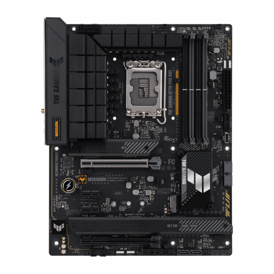
6. M.2 slots (Key M)
The M.2 slots allow you to install M.2 devices such as M.2 SSD modules.
•
•
7. SATA 6Gb/s ports
The SATA 6Gb/s ports allow you to connect SATA devices such as optical disc drives and
hard disk drives via SATA cables.
8. USB 3.2 Gen 1 Type-C
The USB 3.2 Gen 1 connector (USB Type-C
connect a USB 3.2 Gen 1 module for an additional USB 3.2 Gen 1
Type-C
port. The connector provides a data transfer speed of up
®
to 5 Gb/s.
The USB 3.2 Gen 1 module is purchased separately.
9. USB 3.2 Gen 1 header
The USB 3.2 Gen 1 header allows you to connect a USB 3.2 Gen
1 module for additional USB 3.2 Gen 1 ports. The USB 3.2 Gen 1
header provides data transfer speeds of up to 5 Gb/s.
The USB 3.2 Gen 1 module is purchased separately.
10. USB 2.0 headers
The USB 2.0 headers allow you to connect USB modules for additional USB 2.0
ports. The USB 2.0 headers provide data transfer speeds of up to 480 Mb/s.
DO NOT connect a 1394 cable to the USB connectors. Doing so will
damage the motherboard!
The USB 2.0 module is purchased separately.
1-4
Intel
13
& 12
Gen Processors
®
th
th
M.2_1 slot supports PCIe 4.0 x4 mode M Key design and type 2242 / 2260 / 2280
storage devices.
Intel
H770 Chipset
®
M.2_2 slot supports PCIe 4.0 x4 mode M Key design and type 2242 /2260 / 2280
storage devices.
M.2_3 slot supports PCIe 4.0 x4 mode M Key design and type 2242 / 2260 /
2280 / 22110 storage devices.
M.2_4 slot supports PCIe 4.0 x4 and SATA modes M Key design and type 2242 /
2260 / 2280 storage devices.
Front Panel connector
®
) allows you to
®
Chapter 1: Product Introduction
VBUS
SBU2
TX2+
SBU1
TX2-
CC1
GND
VBUS
RX2+
RX1-
RX2-
RX1+
GND
GND
D-
TX1-
D+
TX1+
CC2
VBUS
PIN 1
USB3+5V
USB3+5V
IntA_P1_SSRX-
IntA_P2_SSRX-
IntA_P1_SSRX+
IntA_P2_SSRX+
GND
GND
IntA_P1_SSTX-
IntA_P2_SSTX-
IntA_P1_SSTX+
IntA_P2_SSTX+
GND
GND
IntA_P1_D-
IntA_P2_D-
IntA_P1_D+
IntA_P2_D+
GND
PIN 1
