Dahl VARIODOCK Maintenance Manual - Page 8
Browse online or download pdf Maintenance Manual for Docking Station Dahl VARIODOCK. Dahl VARIODOCK 19 pages.

Functional description
Wheelchair, max. weight 200 kg
3
2
1
Lock plate and spacer
14
Maintenance manual, installation and user guide UK
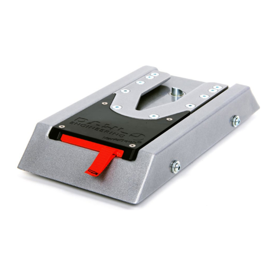
The Dahl VarioDock
TM
(1) is designed to retain manual and
electric wheelchairs, as well as Dahl's seat bases in the vehi-
cle's floor. A control module (6) controls and monitors Dahl
VarioDock
TM
's features, distributes power to the various com-
ponents, as well as receiving and sending signals to and from
the control panel. Wires are included. Do not carry out any
modifications to the supplied wiring or other components. A
lock plate and an 8mm spacer (2) must be fitted under the
5
wheelchair. When the wheelchair is manoeuvred towards the
VarioDock, the wheelchair is guided into place by means of
the lock plate.
When the lock plate is fully engaged in the VarioDock, a
spring-loaded lock pin (3) automatically secures the lock
plate. VarioDock is equipped with a built-in control switch that
indicates whether the lock plate is correctly secured in the
VarioDock. As soon as the lock plate comes into contact with
the locking pin, a warning tone will sound (a high-pitched
6
howl), and the red diode/lamp - LED (A) in the control panel
Control module
will light up until the lock plate is either fully engaged or
else the wheelchair is removed from the VarioDock. With the
wheelchair correctly secured, the warning tone stops and
the green diode/lamp - LED (B) in the control panel will light
up to indicate that the wheelchair is properly secured. The
control panel (5) (see descriptions of control panel's functions
on page 15) is connected to an electromagnet which triggers/
releases the lock pin for approx. 5 or 8 seconds, after which it
4
is automatically locked once more.
In case of an electrical fault, there is a manual emergency
release (4) on the front edge of the VarioDock. The release
arm should be pushed sideways and held in order to release
the wheelchair. You can also use the emergency release tool,
which is delivered with the VarioDock. Fixing parts in the form
of bolts, nuts, washers, etc., are included.
Control panel
A
A
B
B
I
I
H
H
G
G
F
F
To reduce standby power consumption, display can be set to standby mode (see more information under "electrical connection")!
C
C
A
Red diode lights up:
D
D
Wheelchair is not secured and can be
released from the VarioDock
B
Green diode lights up:
Wheelchair is secured.
C
Lamp illuminates when maintenance
is due.
D
Yellow button: Adjusts upwards. Keep
button pressed, to increase step length,
allowing quicker adjustment. Press but-
ton once to adjust in steps of 1mm.
E
Green button: Adjusts downwards. Keep
button pressed, to increase step length,
allowing quicker adjustment. Press but-
ton once to adjust in steps of 1mm.
F
Red button: Unlocks the VarioDock
G
Blue button: Pulls docking station
down to reduce unwanted slack.
H
Symbol for wheelchair's ground
clearance.
I
Display shows the ground clearance of
VarioDock
(wheelchair's ground clear-
TM
ance must be measured, see instructions
E
E
on page 16).
TM
TM
15
Dahl VarioDock™
