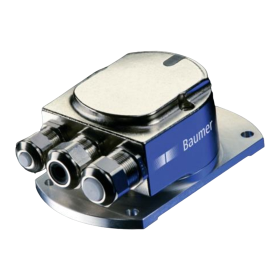
Baumer GNAMG. 213P Series Manual - Page 16
Browse online or download pdf Manual for Accessories Baumer GNAMG. 213P Series. Baumer GNAMG. 213P Series 19 pages. Inclination sensor with profibus-dp interface

7. Terminal assignment and commissioning
7.1. Mechanical mounting
Release both fastening screws of the bus cover.
Carefully loosen the bus cover from the base plate and lift off in the axial direction.
Firmly screw the base plate in place using the fastening holes.
The bus cover must fully rest against the base plate. Any tolerances in mounting the bus cover onto the
base plate might affect the absolute inclination angle.
Alignment of coordinates (y- / y+ / x- / x+) see following diagram.
Installation position – sensing range 15°, 30° und 60°
Baumer_GNAMG_Profibus_MA_EN
07.18
The two-dimensional inclination sensor with a sensing range of
15°, 30° and 60° must be mounted with the base plate in
horizontal position, i.e. parallel to the horizontal line.
The inclination sensor may also be installed upside down, i.e.
turned by 180°.
The sensor can be inclined both in lateral (X-axis) and
longitudinal (Y- axis) direction at the same time. For each
axis a separate measured value is provided.
As default parameter the inclinometer will apply the selected
sensing range to both the X and Y- axis, for example ±15° with
the zero passage being precisely in the horizontal line.
16/19
Baumer IVO GmbH & Co. KG
Villingen-Schwenningen, Germany
