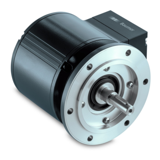
Baumer PMG10 Series Manual - Page 39
Browse online or download pdf Manual for Media Converter Baumer PMG10 Series. Baumer PMG10 Series 41 pages. Absolute encoders with profinet interface
Also for Baumer PMG10 Series: Mounting And Operating Instructions (32 pages)

7. Troubleshooting – Frequently Asked Questions – FAQ
7.1. FAQ: Project Work
7.1.1.
Where do I get an encoder manual?
If ordered, the manual will come as a pdf-file on data carrier (CD). The manual is also available in the Internet
under www.baumer.com. Make sure that the manual applies to your encoder referring to the table at the
beginning of the manual. You will find the encoder type on the product label (for example GXMMW or
GBAMW).
Should your encoder not be on the list please contact Baumer.
7.1.2.
Where do I get the applicable GSDML file?
If included in the order, the GSDML file required for the engineering tool is attached to the encoder on data
carrier (CD). The GSDML file is also available in the Internet under www.baumer.com .
To find out the GSDML file that is applicable for your encoder please use the table at the beginning of the
manual. You will find the encoder type on the product label (for example GXMMW or GBAMW).
Should your encoder not be on the list please contact Baumer.
7.2. FAQ: Operation
7.2.1.
What is the significance of the LEDs provided at the bus cover?
The bus cover provides an integrated multi-color LED indicating the encoder operating status. In particular
upon commissioning and in case of error it provides first information on the system status. For details on the
respective status please refer to chapter 6.2.
Two other, green LEDs are provided near the cable glands for PROFINET connection. These activity LEDs
signal the bus activity, i.e. the data communication on each of the two Ethernet ports.
7.2.2.
How to adapt the resolution?
The encoder resolution in steps per turn („Measuring units per turn") is programmed within the project by
corresponding parameter parameterization in the PROFINET device project.
Usually this is performed by the PLC's engineering software (for example SIEMENS® Step7®) by aid of a
PC.
The encoder resolution is programmable in individual steps between the maximum limit (encoder-specific, for
example 8192 at GXMMW) and the minimum limit of 1 step/turn.
Important: The encoder's total measuring range ("total measuring range (units "hi/lo") must be aligned w
the programmed resolution. If not, this will result in parameterization errors signaled by the LED in the bus
cover flashing red. The maximum total measuring range is calculated by multiplying the resolution (steps per
turn) by the encoder's maximum number of revolutions. Standard resolution is 16 bit (65536 revolutions).
Encoders featuring a 18 bit singleturn resolution (e.g. GBMMW) are capable of a 13 bit resolution (8192
revolutions).
Baumer_BUDE-PROFINET_MA_EN.docx
14.06.2016 / bja
39/41
www.baumer.com
