Baumer HUBNER BERLIN HOG 10 Mounting And Operating Instructions - Page 13

Browse online or download pdf Mounting And Operating Instructions for Industrial Equipment Baumer HUBNER BERLIN HOG 10. Baumer HUBNER BERLIN HOG 10 40 pages. Incremental encoder with connecting cable ölfle
Also for Baumer HUBNER BERLIN HOG 10: Installation And Operating Instructions Manual (36 pages), Installation And Operating Instructions Manual (40 pages), Mounting And Operating Instructions (40 pages), Installation And Operating Instructions Manual (40 pages), Mounting And Operating Instructions (40 pages), Mounting And Operating Instructions (32 pages), Mounting And Operating Instructions (36 pages), Mounting And Operating Instructions (36 pages), Mounting And Operating Instructions (28 pages)
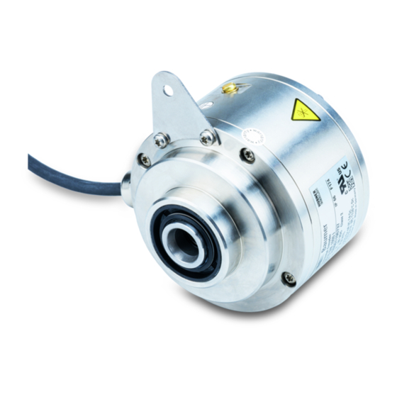
Baumer HUBNER BERLIN HOG 10 Mounting And Operating Instructions
4.3

Schritt 3 - Einseitig offene Hohlwelle

* Siehe Seite 5
See page 5
Antriebswelle einfetten.
Die Antriebswelle sollte einen
möglichst kleinen Rundlauffehler
aufweisen, da dieser zu einem
Winkelfehler führen kann, siehe
Abschnitt 4.7.
Rundlauffehler verursachen Vibrati-
onen, die die Lebensdauer des
Gerätes verkürzen können.
MB071.2T2 - 11068774
53 mm
(35 mm bei/at ød = 20 mm)
L
M6
*
4
Baumer_HOG10-ESL-T2_II_DE-EN (20A1)
4.3

Step 3 - Blind hollow shaft

Zentrierbohrung
Center hole
DIN 332-D, M6x16 mm
4 *
*
3
ød
h6
16 mm ≥ ø20 mm 52 mm (40...52 mm)
20 mm ≥ ø25 mm 34 mm (25...34 mm)
16 mm
Lubricate drive shaft.
The drive shaft should have as less
runout as possible because this can
otherwise result in an angle error, see
section 4.7.
Runouts can cause vibrations, which
can shorten the service life of the
device.
Montage / Mounting
ød1
L
4
10