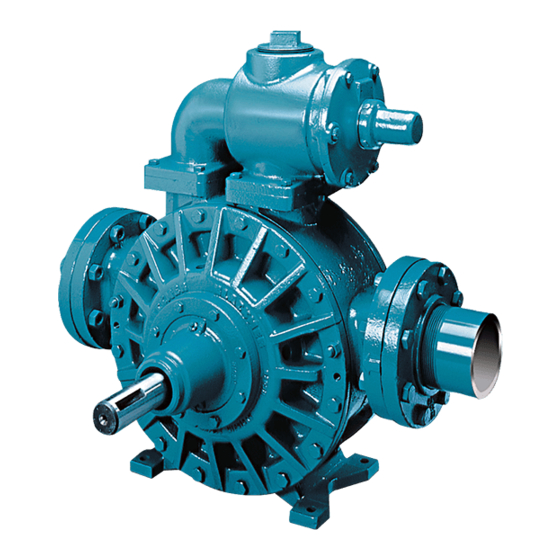
Dover PSG BLACKMER MLXW4B Installation, Operation And Maintenance Instructions - Page 13
Browse online or download pdf Installation, Operation And Maintenance Instructions for Water Pump Dover PSG BLACKMER MLXW4B. Dover PSG BLACKMER MLXW4B 20 pages. Power pumps

MAINTENANCE: MLN4B, MRLN4B
PUMP DISASSEMBLY
NOTICE:
Follow all hazard warnings and instructions provided in
the "Maintenance" section of this manual.
NOTE: The numbers in parentheses following individual
parts indicate reference numbers on the Pump Parts List.
1.
On the outboard (non-driven) side of the pump, remove
the hub capscrews (21D). To disengage the outboard
hub assembly (20C) from the head, two jackscrew holes
are provided in the rim of the hub. Slide the hub
assembly off the shaft with the shaft cover still intact.
NOTE: The sleeve bearing (24) is press fitted into the
hub. Do not remove unless replacement is necessary
(see "Sleeve Bearings").
2.
Remove the two shaft cover capscrews (28) to release
the shaft cover (27) and O-ring (26) from the hub
assembly.
3.
On the opposite (inboard) end of the pump, clean the
pump shaft thoroughly, making sure the shaft is free of
nicks, burrs, or paint that might damage the packing or
mechanical seal when the inboard hub is removed.
4.
PUMPS EQUIPPED WITH PACKING
a.
Back off the packing removal nuts (18A) to reduce
packing friction.
b.
Remove the inboard hub capscrews (21D). Two
jackscrew holes are provided in the rim of the
inboard hub to facilitate removal.
c.
Slide the packing follower (75) and hub assembly
(20C) together off the shaft.
d.
Remove the packing follower (75) removal nuts
(18) and pull the follower out of the hub assembly.
e.
The packing rings (19) and packing washer (58)
can be pulled from the inboard hub with the use of
a corkscrew tool or screwdriver.
NOTE: On pumps equipped with Blackmer Triple-Lip Seal
or a commercial mechanical seal, loosen all setscrews
before removing the hub assembly. For further instructions
on the disassembly and assembly of commercial mechanical
seals, refer to the separate literature accompanying the
mechanical seal.
5.
Remove the head capscrews (21) and head stud nuts
(21C). Two jackscrew holes are provided in the rim of
the head to facilitate removal.
6.
Remove the head (20 or 20A) from the casing (12),
being careful not to nick or scrape the shaft.
7.
The disc (71) will come off with the head assembly and
is attached with four countersunk, allen-head machine
screws (71A) and lockwashers (71B).
8.
From the open side of the pump, grasp the rotor in the 3
and 9 o'clock positions, and gently pull the rotor and
shaft (13) out of the head assembly remaining on the
casing. CAUTION: Use care to avoid injury-the rotor
and shaft is heavy and may have sharp edges.
9.
The remaining head assembly can now be easily
removed. Follow Steps 6 through 8.
10. Depending on the pump application, the liner (41) can be
removed in two ways:
a.
If the pumpage is a clean, non-corrosive liquid, with
low viscosity, the liner can usually be withdrawn from
the casing by prying with two bars. Insert the tips of
the bars into the port openings on either side of the
liner, and partially remove the liner by prying against
the rotor. Use a block under the bar, against the rotor,
to bring the liner the rest of the way out (see Figure
9).
b.
If the pumpage is corrosive, contains a large
concentration of particulate matter, or is high
viscosity, the liner will most likely have to be driven
out of the casing, rather than pried out. To do so, use
a brass or hard wood drift and a hammer and tap
around the diameter of the liner until it is driven out of
the casing.
PARTS REPLACEMENT
1.
If any of the O-rings have been removed or disturbed
during disassembly, they must be replaced with new O-
rings. NOTE: Heat PTFE O-rings in hot water to aid
installation.
2.
Excessive or continuous leakage around the pump shaft
may be an indication of a damaged mechanical seal, worn
packing, or a damaged or worn sleeve bearing.
a.
If a mechanical seal has been leaking, it is
recommended the entire seal be replaced. Refer to
"General Pump Troubleshooting" for possible causes
of seal leakage.
b.
If the packing is leaking excessively, refer to "Packing
Adjustment." If this does not solve the problem, install
a complete new set of packing rings.
c.
If the pump shaft indicates an excessive amount of
radial "play," replace the sleeve bearing (24) in the
hub (20C).
106-A00
Page 13/20
Figure 9 – Liner Removal
