Dover HYDRO DM-500 User Manual - Page 8
Browse online or download pdf User Manual for Dispenser Dover HYDRO DM-500. Dover HYDRO DM-500 14 pages. Warewash dispenser

2.OO installation (continued)
2.O4 Electrical Installation
Installing the Detergent and Rinse Supply Signal Wiring
WARNING!
Before performing any work on the DM-500, you must disconnect the power supply voltage of the dish
machine.
CAUTION!
Verify that electrical grounding is functional and complies with local regulations. Verify that the rated values
of the pump are compatible with those of the power supply. Never install the pump directly in parallel with
inductive loads (e.g. motors/solenoid valves). If necessary, use an isolating relay.
NOTE: All electrical connections must either be in the dish machine control circuit panel or an external junction box. The
dispenser is pre-wired with a multi-conductor electrical cable that may need to be run through a conduit to the location where
hard-wired connections are made on the dish machine. If this is the case use approved water tight conduit that meets local
and national codes
All DM-500 models will have two pairs of signal/power wires that need to be connected to the dish machine.
Using the tables below, connect the signal wires to a compatible voltage source.
Initial Charge Signal
Wire Color
Circuit Voltage
Brown
90 to 260 VAC at 50/60Hz
Blue
90 to 260 VAC at 50/60Hz
Rinse Signal
Wire Color
Circuit Voltage
Brown
90 to 260 VAC at 50/60Hz
Blue
90 to 260 VAC at 50/60Hz
Signal wires should be routed through the appropriate conduit or cable gland in the bottom of the DM-500 to the signal
board shown below. The signal board can be accessed by removing the five Phillips head screws and lifting the front cover
to reveal the unit internals. The Initial Charge signal should be wired to the two screw terminals marked M1 Charge and the
Rinse signal to the two screw terminals marked M2 Rinse. Polarity of these connections does not matter.
2.O5 Setting Dosing Parameters
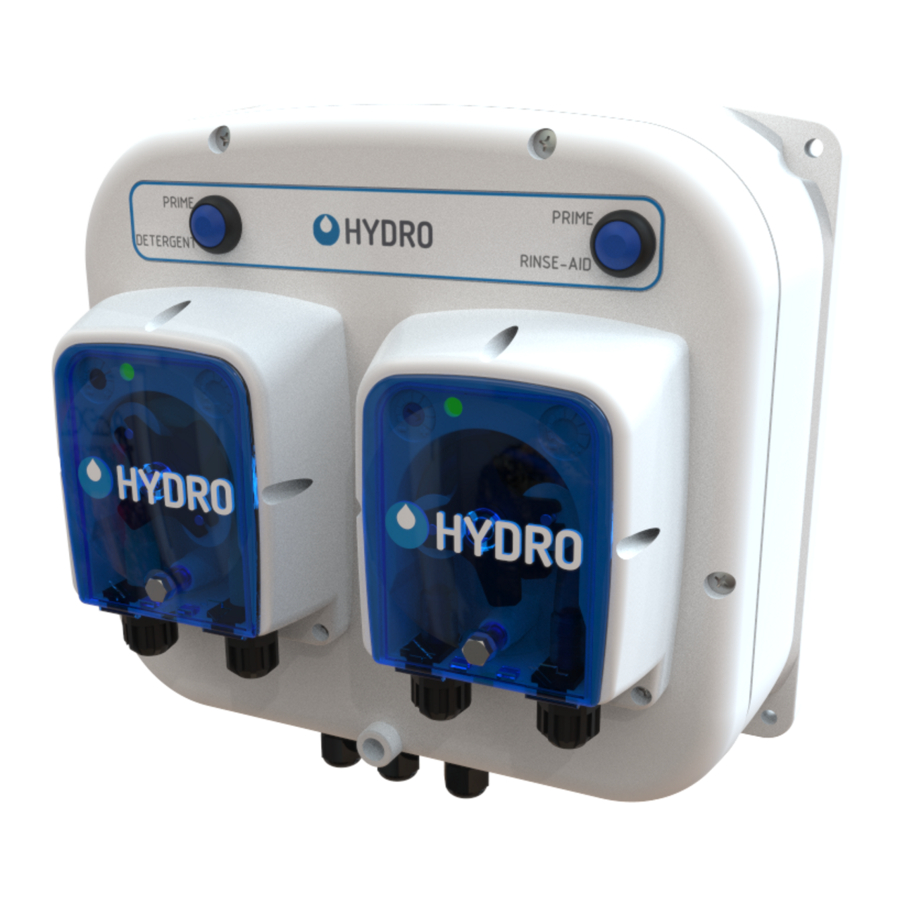
Each DM-500 unit has two pumps, one for detergent (left
side, facing the unit) and one for rinse (right side, facing the
unit) as shown.
Each pump has a priming button and under each pump cover
are potentiometers used to set the dosing time or speed.
In general, the detergent pumps utilize a Santoprene squeeze
tube and the rinse pump a Silicone squeeze tube.
The details for setting the Dosing parameters, for each of the
most popular models, is described on the following pages.
8
Function
Connect to dish machine on/off switch; to trigger an initial charge upon power up.
Connect to dish machine on/off switch; to trigger an initial charge upon power up.
Function
Connect to dish machine rinse solenoid; to trigger detergent and rinse aid dosing for each rack.
Connect to dish machine rinse solenoid; to trigger detergent and rinse aid dosing for each rack.
Rinse Signal Connections
Initial Charge Signal Connections
Detergent
Prime
Detergent
Pump
UL Model Shown
Rinse
Prime
Rinse
Pump
Conduit
Fitting
