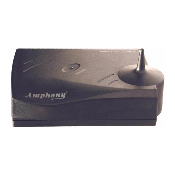
User and Installation Guide
Placing the transmitter and amplifiers
For best reception, we recommend that each amplifier be placed within the line
of sight from the transmitter. If possible, each amplifier should be placed right
side up with its front toward the transmitter.
The transmitter should be placed at an elevation such that there are no
obstacles between the transmitter and amplifiers (line of sight) in an area where
there will be the least amount of traffic. We suggest that you place the
transmitter on top of your audio source. Example 1 below shows the optimum
placement of the transmitter and an amplifier. If no line of sight is possible, place
the transmitter and amplifiers such that there is the minimum possible number of
walls and obstacles between the transmitter and each amplifier.
The amplifiers can also be placed as shown in example 2.
of-sight connection exists and the operating range is reduced.
You can mount the amplifiers vertically by using the 2 screw openings at the
bottom of each amplifier. If the amplifiers are mounted vertically, the operating
range is reduced compared to mounting the amplifiers right side up.
Each amplifier incorporates a directional antenna which prefers signals
transmitted toward the front of the amplifier. Therefore, the front of the amplifiers
should always be facing toward the direction of the strongest transmitter signal.
By properly orienting each amplifier, interference from other signal sources can
be minimized.
We suggest that you experiment with placement in order to find the best location
for the transmitter and amplifiers.
Note:
This product will not work properly from within an enclosed metal cabinet.
Transmitter
line of sight
Example 1: Amplifier placed
on top of a speaker
Amplifier
Speaker
In this case, no line-
Transmitter
indirect connection
(reflected signal)
Example 2: Amplifier mounted
vertically behind a speaker
R
Amplifier
Speaker
Page 5

