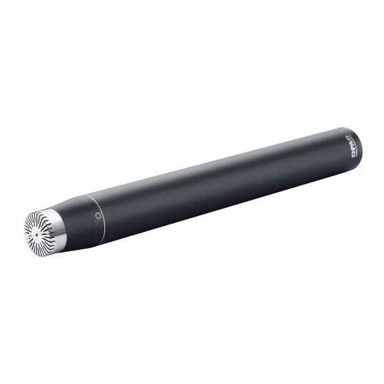
DPA 3529-A User Manual - Page 9
Browse online or download pdf User Manual for Microphone DPA 3529-A. DPA 3529-A 11 pages. Omnidirectional microphones
Also for DPA 3529-A: User Manual (13 pages)

3529-A AND 3530-A KITS INCLUDE
2 x 4006
Omnidirectional Microphone, P48, matched (3530-A)
or
2 x 4003
Omnidirectional Microphone, 130V, matched (3529-A)
UA0836
Stereo Boom with Holders
2 x DD0251
Near-field Grid, Silver
2 x DD0297 Diffuse-field Grid, Black
2 x UA0777
Nose Cone
2 x UA0638
Windscreen for Ø16mm (0.63in) Microphone
2 x L110C
Acoustic Pressure Equaliser, 110mm (4.33in) Cylinder
2 x L30B
Acoustic Pressure Equaliser, 30mm (1.18in) Ball
2 x L40B
Acoustic Pressure Equaliser, 40mm (1.57in) Ball
2 x L50B
Acoustic Pressure Equaliser, 50mm (1.97in) Ball
2 x DAO0130 130V Microphone Cable, 5m (16.4ft) (3529-A)
HMA4000
Hi-Voltage Microphone Amplifier, 2 channel (3529-A)
16
CARE OF MICROPHONE
It is important to bear in mind the following points with regards to
mounting, microphone care and the use of accessories:
The microphone cartridge is tightly secured to the main body hous-
ing, and no attempt should be made to remove it. If a replacement
cartridge is required, contact your local DPA Microphones represen-
tative.
Types 4003 and 4006 are supplied with an additional Diffusefield
Grid DD0297 (see "Technical Description" and "Full Specifications").
On delivery, the normal protection grid is screwed on to the car-
tridge housing and normal finger torque is required to remove it. Do
not try to unscrew or tighten the protection grids with any kinds of
tools as both surface and thread might be damaged.
Use of windscreen is recommended when microphones are used in
dirty or dusty environments.
When not in use, the microphone should be disconnected and kept
in the case supplied.
17
