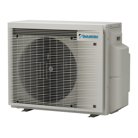
Daikin 2MXM50A2V1B Installation Manual - Page 15
Browse online or download pdf Installation Manual for Air Conditioner Daikin 2MXM50A2V1B. Daikin 2MXM50A2V1B 20 pages. R32 split series

9.3.1
To turn ON heat mode lock
1 Remove the top plate (2 screws) and the front plate (8 screws).
2 To set heat mode lock remove the S99 connector.
3 To reset the heat pump mode (cooling/heating), plug the
connector back.
a
2×
8×
a
Front plate
b
Top plate
c
S99 connector
Mode
Heat pump (cooling, heating)
Heating only
4 Reinstall the top plate and the front plate.
INFORMATION
Forced operation is also available in heating mode.
9.4
About standby electricity saving
function
The standby electricity saving function:
▪ turns OFF the power supply to the outdoor unit and,
▪ turns ON the standby electricity saving mode on the indoor unit.
The standby electricity saving function works with following units:
FTXM, FTXP, FTXJ, FVXM, ATXF
If another indoor unit is used, the connector for standby electric
saving MUST be plugged in.
The standby electricity saving function is turned OFF before
shipping.
9.4.1
To turn ON standby electricity saving
function
Prerequisite: The main power supply MUST be turned OFF.
1 Remove the service cover.
2 Disconnect the selective standby electricity saving connector.
2MXM40+50A
R32 Split series
3P600450-5L – 2021.12
c
b
S99 connector
Connected
Disconnected
3 Turn ON the main power supply.
10
Commissioning
NOTICE
General
commissioning
commissioning instructions in this chapter, a general
commissioning checklist is also available on the Daikin
Business Portal (authentication required).
The general commissioning checklist is complementary to
the instructions in this chapter and can be used as a
guideline and reporting template during the commissioning
and hand-over to the user.
NOTICE
ALWAYS operate the unit with thermistors and/or pressure
sensors/switches. If NOT, burning of the compressor might
be the result.
10.1
Checklist before commissioning
1 After the installation of the unit, check the items listed below.
2 Close the unit.
3 Power up the unit.
The indoor unit is properly mounted.
The outdoor unit is properly mounted.
The system is properly earthed and the earth terminals
are tightened.
The power supply voltage matches the voltage on the
identification label of the unit.
There are NO loose connections or damaged electrical
components in the switch box.
There are NO damaged components or squeezed
pipes on the inside of the indoor and outdoor units.
There are NO refrigerant leaks.
The refrigerant pipes (gas and liquid) are thermally
insulated.
The correct pipe size is installed and the pipes are
properly insulated.
The stop valves (gas and liquid) on the outdoor unit are
fully open.
Drainage
Make sure drainage flows smoothly.
Possible consequence: Condensate water might drip.
The indoor unit receives the signals of the user interface.
The specified wires are used for the interconnection
cable.
10 Commissioning
checklist.
Next
to
the
Installation manual
15
