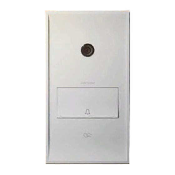
Amroad AMROAD P3 Quick Installation Manual
Browse online or download pdf Quick Installation Manual for Accessories Amroad AMROAD P3. Amroad AMROAD P3 2 pages. Door station
Also for Amroad AMROAD P3: Installation Manual (12 pages)

amroad P3
quick installation guide
for system integrators
Product code: Amroad db3100r
© 2012 AmRoad Technology Inc. All rights reserved.
Amroad, Amroad p3, the Amroad logo and other Amroad marks are owned by AmRoad Technology Inc. and
may be registered. All other trademarks are the property of their respective owners.
qig : 800-0000038-00-00 - English version
Package contents
1
2
14
1.
Front panel
2.
Main unit
3.
Metal wall box
4.
2-pin terminal block + cord end terminal (×2)
5.
5-pin terminal block + cord end terminal (×5)
6.
H type terminal connector for power cord
7.
Screws for firmness in solid concrete (×4)
Product overview
This Quick Start Guide only describes how to install our product into stone slabs (ie marble).
However, the included metal wall box can be installed into many different types of wall.
By tightening the 4 included screws (#7) on the side of the wallbox, you will increase its firmness
into concrete-based installation.
3
4
7
8
5
9
10
6
8.
Pin-Torx security screws (×2)
9.
Long Phillips screws (×4)
10.
Relay board
11.
Wall plugs (×4) + self tapping screws (×4)
12.
L-shaped key for security screws
13.
Blank rfid card
14.
Button extraction tool
installing the device
cutting the hole
1.
By using a bubble level, draw a rectangle of 187×97 mm on the slab. The lower side of the
rectangle should be located at 140 cm from the ground.
2.
Using the lines as external limit, cut a rectangular hole into your slab. The depth of the
wallbox is about 50 mm.
11
12
13
installing the wall BoX
1.
Remove one of the knock-outs.
2.
Put the wall box (#3) into the cavity and mark the position of the four mounting holes.
3.
Drill the four holes with a diameter of 5 mm.
4.
Insert the four wall plugs (#11).
5.
Insert the corrugated tube into the removed knock-out.
6.
Place the wallbox into the cavity and tighten the screws (#9).
wire and caBle connection
1.
Connect cables and wires according to the diagram above.
2.
Connect the black wire (ground wire) to the wall box. Remember to tighten the screws on
both sides. In order to prevent power surge and lighting strike from damaging the device, the
wallbox should be connected to the earth wire of the building.
installing main unit and front Panel
1.
Place the main unit (#2) into the wallbox and tighten the four Phillips screws (#9).
2.
Withour removing the protective film, firmly press the front panel (#1) against the device
until it touches the wall.
3.
Lift up the bell button using the extraction tool (#14).
4.
Tighten the 2 security screws (#8) with the l-shaped key (#12).
5.
Close the key by pressing it until it snaps and re-apply the protective film on the front panel.
