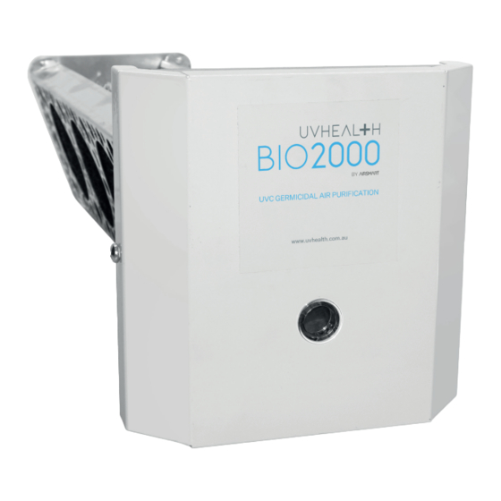
Airsmart Uvhealth BIO2000 Installation Manual - Page 9
Browse online or download pdf Installation Manual for Air Cleaner Airsmart Uvhealth BIO2000. Airsmart Uvhealth BIO2000 16 pages. Germicidal uv-c air purification

5.2
UVHEALTH BIO2000 UNIT INSTALLATION
1.
Choose a location for the UVHealth BIO2000 unit, with
the following considerations:
Figure 8A: Positioning the UVHealth BIO2000 in the supply air duct
75mm clear zone around UV lamp
to prevent damage from UV light
Figure 8B: Positioning the UVHealth BIO2000 in a return air duct
Where the BIO2000 can not be installed in the duct unit or
adjacent ductwork, then the BIO2000 should be installed
into a custom transition, as shown in Figure 9.
W
600x600
Maintenance
Access
Flex duct connection to suit required diameter
Figure 9: Positioning the UVHealth BIO2000 in a custom
transition piece
75mm clear zone around UV lamp
to prevent damage from UV light
C:\Users\user\Mod Cons Heating & Cooling PTY LTD\Jobs - Documents\ZZZ DETAILS\FROM JIM'S PORTABLE HD\Do Not Amend - RCD CLEARANCE.dwg, Model
C:\Users\user\Mod Cons Heating & Cooling PTY LTD\Jobs - Documents\ZZZ DETAILS\FROM JIM'S PORTABLE HD\Do Not Amend - RCD CLEARANCE.dwg, Model
D
BIO1000 or BIO2000 unit
H
Dimensions to fit
BIO1000
BIO2000
Figure 10: Minimum dimensions for transition piece
The unit will reduce organic build up on an HVAC cooling/
heating coil by illumination with germicidal UV-C rays.
Locate the unit such that the maximum surface area of the
coil is illuminated, while installing as close to the coil as
possible without damage to the coil.
Use care to avoid damage to the coil and any wiring
or other components while installing the UVHealth
BIO2000 unit.
To prevent water damage or electric shock, DO
NOT mount unit under a humidifier or near the
condensate drain pan.
•
The unit may be installed on either the supply or return
plenum.
•
The unit may be installed in upflow, downflow, or
horizontal flow ducts and plenums.
•
The unit may be installed directly onto a sheet metal
air duct or plenum, or onto fiberglass ductboard when
installed using the included Ductboard Mounting Plate.
See Figure 11.
Figure 11: Marking the mounting hole using the Ductboard
Mounting Plate as a template
2.
Attach the quick connect power cord and plug in to
any standard electrical outlet. Verify lamp operation by
looking through the view port on front cover.
Note: Continuous UV-C germicidal lamp operation is
recommended. Cycling the UV-C germicidal lamp on
and off degrades lamp performance much faster and
shortens the filament life.
UVHEALTH BIO2000 Installation Manual
Minimum Dimensions
W
H
460
460
125
460
460
300
D
9
