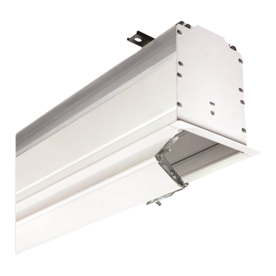
Draper XT1000V Installation & Operation Instructions
Browse online or download pdf Installation & Operation Instructions for Projection Screen Draper XT1000V. Draper XT1000V 7 pages. Electric projection screen

Ultimate Access E and V
Electric projection screen
Overview - Components
Mounting Bracket
Electrical Cutout
Tab Tensioning
"V" Dowel
Shipping Brackets Attached
to Dowel and Screen Case
(V Screens Only)
Please Note: Shipping brackets must remain in place
until product has been mounted and connected to
power
(see Sections 1 and 4 in this document.)
Also, DO NOT operate screen before removing
shipping brackets from screen case.
Read and understand all warnings
Contents
Overview - Components ...............................................................................................1
Section 1 - Removing Shipping Brackets
PLEASE READ - Safety Information ............................................................................2
Section 2 - Hanging Screen .........................................................................................3
Section 3 - Bottom Access Panel/Trap Door Opening and Closing .....................3
Section 4 - Motorized Roller/Fabric Installation ......................................................4
Section 5 - Motorized Roller/Fabric Removal ..........................................................4
Section 6 - Operation ...................................................................................................5
Leveling Bracket
Hoisting Bracket
"V " Fl ex ib le V in yl
V ie w in g S u rf ac e
.
CAUTION
..............2
Hoisting Bracket
"E " Fr ee H an g in g
V ie w in g S u rf ac e
TOOLS REQUIRED
PENCIL
HARDWARE
before beginning installation.
(page 2)
Section 7 - Tab-Tension Adjustment Procedure ......................................................5
Section 8 - Electrical Connections ............................................................................5
Section 9 - Limit Adjustments .....................................................................................5
Section 10 - Case Length Dimensions .......................................................................6
Section 11 - Case Width Dimensions .........................................................................6
Section 12 - Mounting Bracket Dimensions .............................................................6
Section 14 - Wiring Diagrams ......................................................................................7
Ultimate Access screen, call your dealer or Draper, Inc.
© 2022 All Rights Reserved
INSTRUCTIONS
INSTALLATION & OPERATION
Mounting Bracket
Trim Flange
"E" Dowel
POWER DRILL
TAPE MEASURE
LEVEL
(by others)
........................7
If you have any difficulties installing or servicing your
Draper, Inc. | 411 S. Pearl St. Spiceland, IN 47385
draperinc.com | 765.987.7999 | 800.238.7999
|
FORM: UltimateAccess_Inst22
