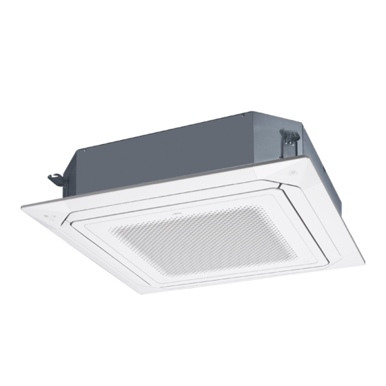
AirStage AUXK030GLEH Installation Manual - Page 4
Browse online or download pdf Installation Manual for Air Conditioner AirStage AUXK030GLEH. AirStage AUXK030GLEH 13 pages.

3.2. Installation dimension
Ceiling height is as shown in the figure.
256 mm or more (AUXM018,024,030)
298 mm or more (AUXK018,024,030,034,036,045,054)
Strong and durable ceiling
3,000 mm or more
1,000 mm or more
H: Maximum height from floor to ceiling
Function setting
AUXM
018/024/030
Standard mode
3,000
High Ceiling mode
3,500
* Be sure to make the function settings with the remote controller according to the
installed ceiling height.
Discharge direction setting
• The discharge direction can be selected as shown below.
4 direction
3 direction
* Select the most appropriate airflow direction from 3 or 4 directions according to the
shape of the room and the installation position.
* When changing the number of outlets, we recommend using the optional AIR OUTLET
SHUTTER PLATE KIT to close the outlet.
* For the specific closing pattern, please refer to the attached AIR OUTLET SHUTTER
PLATE KIT'S MANUAL. (Do so before installing the cassette grille as it will be installed
on the body.)
3.3. Installing the unit
Install the air conditioner in a location which can withstand a load of at least 5 times the
weight of the main unit and which will not amplify sound or vibration. If the installation
location is not strong enough, the indoor unit may fall and cause injuries.
If the job is done with the panel frame only, there is a risk that the unit will come loose.
Please take care.
3.3.1. Position the ceiling hole and hanging bolts
(1) Positions of the ceiling opening, hanging bolt pitch, piping and ducts.
• Ceiling opening and hanging bolt pitch. (unit: mm)
950 (Cassette grille)
20 to 45
860 to 910 (Ceiling opening)
840 (Indoor unit)
796 (Hanging bolt pitch)
130
200
En-3
1,800 mm to H
Obstruction
Floor
H (mm)
AUXK
018/024/030/034
3,200
3,600
*1: Please ensure sufficient
service access during
100 mm or more *1
installation.
WARNING
20 to 45
Dimension (mm)
Type
50
A
AUXM
246
AUXK
288
• Refrigerant piping and drain piping positions. (unit: mm)
Drain pipe
1,500 mm
(Connect the attached
or more
drain hose)
• Distribution ducts and fresh air inlet positions.
Fresh air
inlet position
AUXK
036/045/054
3,200
4,200
Drain pipe
Distribution duct connecting port
NOTE:
Conduct proper insulation when connecting the
distribution ducts and fresh air inlet.
* When sucking in the fresh air, please detach the
insulation affixed to the drain pan.
(2) Setting the positions of hanging bolt and
ceiling opening.
• Use an installation template (packaging top
surface) to set the positions of the hanging bolt
and ceiling opening and drill holes.
(3) Hanging structure.
• Select a strong structure for the hanging location.
• If necessary, reinforce the hanging bolt with quakeproof columnar support material to
prevent shaking.
• Use hanging bolts of M8 to M10.
3.3.2. Hanging preparations
• Firmly fasten the hanging bolts as shown
in the figure or by another method.
• Install the hanging bolts at a place
where they would be capable of holding
a weight of at least 490 N per bolt.
3.3.3. Body installation
Perform final tightening by tightening the double nut firmly.
Be sure to install the body horizontally and adjust the height below the body and the
ceiling surface properly.
(1) Install the attached
washer and nut (prepared
on site) onto the hang-
ing bolt.
(2) Hook the body onto the
hanging bolt.
(3) Adjust the dimensions of
the ceiling surface from
the body.
After installing the
cassette grille, you can
make fine adjustment of
the height of the body.
B
For details, refer to the
installation manual of the
256
cassette grille.
298
Drain pipe
Liquid pipe
342
Distribution duct
connecting port
Detailed diagram of distribution duct con-
necting port (4 sides)
Refrigerant pipe
Ø 144
(bolt pitch)
Hole-in anchor
Hole-in plug
WARNING
Washer
(Accessories)
Washer
(Accessories)
10 to 15 mm
Gas pipe
293
45
100
100
83
83
Cut out
352
10 × Ø 3.2 hole
Ø 70
250
(cut out)
4 × Ø 3.2 hole
Fresh air inlet position
Insulation
Fresh air
inlet position
Concrete
Insert
Hanging bolt M10
(locally purchased)
Hanging bolt
(locally purchased)
Nut A
(locally purchased)
30 mm or more
After installing
the body, tighten
the nuts.
Nut B (Double Nut)
(locally purchased)
