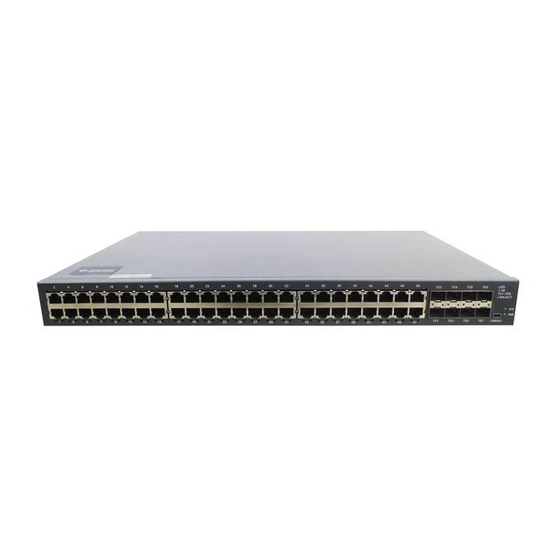
Bdcom S2956 series Hardware Installation Manual - Page 18
Browse online or download pdf Hardware Installation Manual for Switch Bdcom S2956 series. Bdcom S2956 series 19 pages.

Chapter 5
The part describes how to remove the fault from the switch.
5.1
Fault Separation
The key for resolving the systematic faults is to separate the fault from the system. You
can compare what the system is doing with what the system should do to detect the
fault. You need to check the following subsystems:
Power and cooling systems—power and fan
Port, cable and connection—ports on the front template of the switch and the
cables connecting these ports
5.1.1 Faults Relative with Power and Cooling System
Do the following checkups to help remove the fault:
When the power on-off is at the "ON" location, check whether the fan works
normally. If the fan does not work well, check the fan.
If the switch is too hot, check whether the air outlet and air inlet are clean and
then do relative operations in section 2.3 "Requirements for Common Locations".
The working temperature of the switch is from 0 to 40 Celsius degrees.
If the switch cannot be started and the PWR LED is off, check the power.
5.1.2 Faults Relative with Port, Cable and Connection
Do the following checkups to help remove the fault:
If the port of the switch cannot be linked, check whether the cable is correctly
connected and whether the peer connection is normal.
If the power on-off is at the "ON" location, check the power source and the
power cable.
If the console port does not work after the system is started up, check whether
the console port is set to a baud rate of 9600 bps, eight data bits, no sum check bit
and one stop bit.
5.2
LED Description
The LED indicator shows that the switch is running. The following table shows the
indicators of the S2956 switch and their description:
No.
Hardware Fault Analysis
Abbrev.
Name
S2956 Hardware Installation Manual
Remarks
- 16 -
