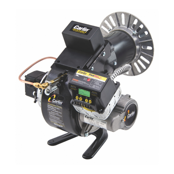
Carlin 200CRD Installation And Operating Instructions Manual - Page 2
Browse online or download pdf Installation And Operating Instructions Manual for Burner Carlin 200CRD. Carlin 200CRD 8 pages.

GARUN
III BURNERS
SPECIFICATIONS
—
DIMENSIONS
STANDARD MODELS
—
7", 9", and 1 1"
air tube, flange
or
ped¬
estal mounting.
CAPACITIES
—
Model 200CRD, 2.00
to
5.00 GPH.
Model 20
1
CRD, 4.00
to
5.50 GPH.
(GPH
ratings
are
based
on sea
level
to
2,000 ft.
elevation. For
every 1,000 ft.
rise over 2,000 ft., reduce the maximum GPH
rating by 4 percent.)
MOTOR
—
3450 RPM, 115-volt, 60-Hz,
l-phasc. Va H.P. with
thermal overload protection.
48-frame with "N" flange per
NEMA specifications.
TRANSFORMER—
120V/
10,000V.
23
milliampcrcs, 60
Hz.
Shielded against radio and TV interference. UL listed for
continuous duty; interchangeable.
FUEL UNIT
—
Standard style with
7/ic"
shaft diameter. 3450
RPM. Designed for quick cut-off. Single-stage with built-in
strainer and pressure regulating valve. Strainer and nozzle
capacities exceed the maximum rating
of
the burner. Equipped
with
easy-flow
bleed valve.
OIL
VALVE
—
Standard burner equipped with quick opening
and
instantaneous closing
magnetic
solenoid valve
for smooth,
clean
starts and
sharp, clean cut-offs.
COMBUSTION HEAD and ELECTRODE ASSEMBLY
—
Unique
CRD
"controlled flame retention"
design provides adjustable
aerodynamics
so that air pattern and
velocities
can be op¬
timized for
any
nozzle size within the entire
range of
the
burner without
a
change of parts.
High-chromium stainless steel electrodes with porcelain
insulators fully
glazed and
counterbored
for
maximum clean-
ability and safety. Stainless steel heat shield
on
air tube pre¬
vents
overheating of combustion head and nozzle.
NOZZLE
—
Stainless
steel
with fine-mesh strainer. Spray
angle
and spray pattern specified for optimum
combustion.
BLOWER WHEEL
(FAN)
—
Precision
balanced. Mounted directly
on
motor
shaft.
Dimensions: Model 200CRD, 5Va" OD x 3Vi" width.
Model 201 CRD, 5%" OD
x 4" width.
HOUSING
—
Rugged grey iron casting line-bored for
accurate
alignment
of
motor
and pump
shaft centerlines. Streamlined
fan-scroll for more positive
and
quieter air delivery.
COUPLING
—
Flexible-type, oil-resistant, short
length
with slip-
on
end
fittings for easy service.
CONTROLS
—
Thermostat and limit control.
120-volt, 60-Hz
burner-mounted primary
relay
with cadmium cell flame de¬
tector.
Complies with UL requirements.
SHIPPING WEIGHT
—
Approximately 65 lbs.
DIMENSIONS ARE APPROXIMATE
MOUNTING
PLATE
TYPICAL FLANGE APPLICATIONS
EFFECT OF BACK PRESSURE ON MAXIMUM FIRING RATES
The maximum firing
rates
of
5.00
gph
for Model 200CRD
and 5.50 gph
for Model 201CRD
are based on operation with
zero to
slightly
negative
pressure such as 0.01"
to
0.03" W.C.
draft
over the fire as normally encountered
in
a
natural draft unit.
When
a
unit is designed for forced draft operation with a positive pressure
(back pressure)
over the fire, the maximum air capacity
of
the burner is reduced in proportion
to
the
amount
of pressure. As
a
result, the maximum firing
rate
is also reduced. The graph,
right,
shows the
maximum
firing
rate
in gph of each
model with
various
amounts
of pressure in the
combustion
chamber.
As an example, the
Model 200CRD
has a
maximum
firing
rate
of
just over 4 00 gph when
fired against a back
pressure
of 0.20" W.C.
Note: Installation
of
Models 200CRD and 201CRD in trailers or
furnaces
with more than
0.1"
back pressure or with undersized breechlngs (See Table
A)
or chimneys
(See
Table
B)
Is
not recommended
unless
the unit has been pre-tested with these burners under these
conditions.
x
0.
o
I
UJ
5
a:
o
z
£
u.
X
<
z
Table A
Table B
Max. Firing Rate
GPH
Min.
Diameter
Smoke Pipe (Ins.)
1.80
6
2.50
7
3.10
8
4.50
9
7.00
10
RECTANGULAR
ROUND
Max. Firing
Rate
Chimney Size
Liner Size
Max.
Firing
Rate
Uner Size
GPH
Nom. (Ins.)
(Ins.)
GPH
(Ins.)
2.10
8x8
63/4
X
63/4
1.30
6
3.50
8x
12
6i/2
x
101/2
1.80
7
5.30
12
x 12
93/4
X
93/4
2.50
8
7.70
12x16
91/2
x
131/2
4.50
10
5.60
11
Add 5' to height when two units
are connected
to
one chimney.
DRILL
S TAP
3 HOLES
3/fl
-
16
FLANGE
UNIVERSAL
FLANGE
MOUNTING
PLATE
OPENING
REFRACTORY
OR
HIGH TEMP
INSULATION
MODEL
ZOO CRD
MODEL
0.0 020 0.40 0.60 0.80
LOO 1 ZO
PRESSURE
IN
COMBUSTION
CHAMBER
(INS
W
C
)
