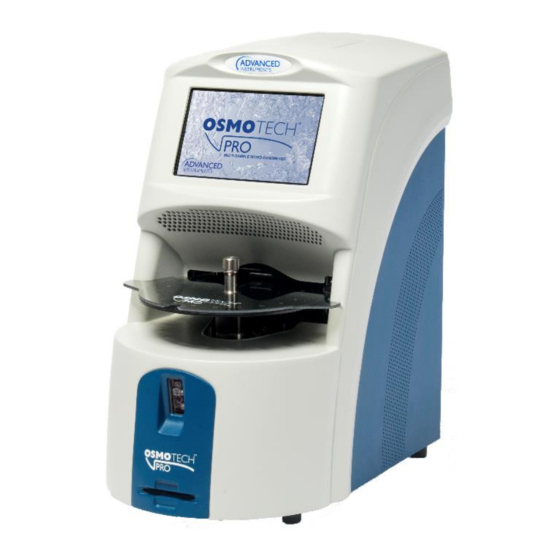
Advanced Instruments OsmoTECH PRO Quick Start Manual
Browse online or download pdf Quick Start Manual for Medical Equipment Advanced Instruments OsmoTECH PRO. Advanced Instruments OsmoTECH PRO 5 pages. Sample probe motor
Also for Advanced Instruments OsmoTECH PRO: Quick Start Manual (4 pages)

Replacement Procedure 222123PM
OsmoTECH ® PRO Block Probe
Scope
This document describes how to replace the block
probe (p/n 222123R) on the OsmoTECH® PRO
Multi‑Sample Micro‑Osmometer. It is intended for use in
conjunction with service procedures that require access
to the OsmoTECH PRO interior.
Tools required
•
#1 and #2 Phillips screwdrivers
•
5/16" nut driver
•
7/64" and 9/64" Allen wrenches
30 µL sample tube
•
•
Static grounding wrist strap
Parts and materials required
Replacement part 222123R
Related documents
•
OsmoTECH PRO Disassembly and Reassembly
(p/n 222202PM)
•
OsmoTECH PRO Service Guide (p/n 222006EN)
Safety notices
WARNING:
Hazardous Voltage. Power cord must
be disconnected to prevent electrical shock.
NOTICE:
Internal components may be damaged
by static electricity. A static grounding wrist
strap must be worn during this procedure.
NOTICE:
Improper connections may cause
damage to the instrument.
Two Technology Way / 781-320-9000
Norwood, Massachusetts 02062, USA
800-225-4034
Fax:781-320-8181
aicompanies.com
Hot-Line Technical Service: Advanced Instruments and worldwide distributor network provides 24/7
comprehensive customer service and technical support.
©2019 Advanced Instruments. All trademarks are the property of their respective companies.
Disconnecting the control PCB
1.
Remove the rear and side enclosure as explained in
OsmoTECH PRO Disassembly and Reassembly.
2.
Remove the cable clamp [A] that secures the C10
sample probe cable and the C11 block probe cable
to the side of the power supply and controls
assembly.
A
3.
Unplug the C10 and C11 connectors from the control
PCB.
4.
Disconnect the B1, B2, B3, B4, B6, B7, B8, B9, and
B10 connectors on the motor/sensor cable harness
from their mating connectors.
5.
Disconnect the A1, A2, A3, and A4 connectors on
the cooling system harness from their mating
connectors.
222123PM Rev 0
