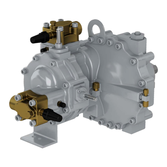
Carlyle 06T Application Manual - Page 9
Browse online or download pdf Application Manual for Air Compressor Carlyle 06T. Carlyle 06T 20 pages. Screw compressor

3.0 Oil Management System
3.1 Oil Separator
An oil separator is required on all Carlyle screw compressor
systems. The screw compressors do not have an oil sump
for storage of the system oil charge. The selection of the oil
separator should consider the desired oil circulation rates as
well as storage of oil for the entire bank of compressors.
3.2 Piping Configuration
The inlet piping from the compressor to the separator
should follow a few simple rules:
1. The discharge header should be one consistent size
throughout.
2. Step changes in the line diameter should be avoided
with the exception of the reducing fittings required to
couple to the oil separator.
To optimize the performance of the vortex separators, they
should be piped with a 90° elbow in the discharge line (turn-
ing in the same direction as the vortex) just prior to entering
the oil separator.
Inlet piping to the separator must be sized to maintain
enough velocity at the minimum load condition of the rack.
The minimum velocity should be no less than 20fps (feet per
second) (6.1 mps [meters per second]) and the maximum
velocity should be no more than 75fps (22.9 mps). Velocities
above this limit may result in excessive pressure drop
across the oil separator.
Steel oil piping is not recommended for use with 05T/06T
screw compressor applications.
3.3 System Oil Charge
The system oil charge will vary depending on the size of the
separator used, size of the oil cooler (where applicable), oil
manifold, and natural refrigerant piping traps and coating.
3.4 Oil Level Switch
An oil level switch is required and must be located in the bot-
tom of the oil separator or reservoir. The level switch is used
to monitor the oil level and act as a safety in case of low oil
levels. The float switch must be wired to open all the com-
pressor control circuits on the rack during cases of low oil
level. The float switch will be normally closed when ade-
quate oil is in the separator or reservoir sump. The oil level
switches are generally pilot duty devices, their electrical
switching capacity should be validated to ensure they are
not overloaded. During transient conditions where signifi-
cant foaming is present in the oil sump, the oil level switch
may rapidly fluctuate causing nuisance tripping. System
controls must be designed to discriminate these nuisance
conditions from real low oil level conditions.
3.5 Oil Pressure Protection
The 05T/06T screw compressors are lubricated using oil fed
from the high pressure side of the system. To ensure ade-
quate lubrication the pressure of the oil feed to each com-
pressor must be a minimum of 45psi (3 bar) above suction
pressure. Care should be taken to avoid large pressure
drops between the oil separator (discharge pressure) and
this oil feed to the compressor (oil pressure). See Section
3.9 for addition details on these pressure drops.
The LonCEM protection module provides comprehensive
oil pressure protection through the use of discharge pres-
sure, oil pressure and suction pressure transducers to mon-
itor operating pressures.
Refer to the LonCEM Installation and Operations Guide for
a complete description of the application and operation of
the LonCEM module.
3.6 Oil Solenoids
A normally closed solenoid is required in the oil feed line to
each compressor, see Section 3.12 for oil system schemat-
ics. To avoid excessive pressure drop, the internal port size
must be 5/16 in. diameter or larger. An oil strainer is re-
quired before each oil solenoid (or as an integral part of the
solenoid). The solenoid will protect the compressor from be-
ing filled with oil from the high pressure oil feed line during
the off cycle. Each solenoid must be properly wired to the
Carlyle LonCEM (per installation instructions) of the com-
pressor it is controlling. The valve must be open during the
on cycle and closed during the off cycle. Manually adjust-
able valves must be checked to ensure the manual opera-
tion stem is completely back seated (ensuring the valve is
closed when the solenoid is de-energized).
CAUTION
When testing the control circuit without the compressor
running, the oil line must be valved off so that the com-
pressor will not be filled with oil.
Whenever possible use control logic to determine that the
compressor is running before opening the oil solenoid.
3.7 Discharge Temperature Control
The 06T semi-hermetic screw compressors can be operat-
ed for most applications without external oil cooling. 05T
open drive screw compressors require external oil cooling
any time the system discharge temperature may exceed
180°F(82°C). The CARWIN Selection Software can be
used to estimate the discharge temperature for a given ap-
plication. The CARWIN tool allows for selections to be made
with or without an oil cooler.
See Operating Envelopes in Section 2.1 for operating condi-
tions that may require the use of external oil cooling.
An external oil cooler will reduce both the discharge and
motor temperatures within their respective limits, however,
additional refrigerant injection may still be required. For
screw compressors this injection is either by the motor cool-
ing valve and/or at the rotor injection port. Because refriger-
ant injection for motor and discharge cooling flows into the
screw rotor chamber after the suction gas is trapped, com-
pressor capacity is not significantly affected. Under some
conditions the motor cooling valve alone can accommodate
this extra cooling requirement. For conditions requiring addi-
tional discharge temperature cooling, a desuperheating
valve is recommended. It should be selected to start open-
ing at a discharge temperature of 190°F (88°C) and be fully
open at 200°F (93.3°C). The bulb should be located on the
discharge line within 6 inches (15cm) of the compressor dis-
charge service valve. A properly sized solenoid valve should
9
