CommScope 360-iP-PMAX-GS3-24 Instruction Sheet - Page 3
Browse online or download pdf Instruction Sheet for Cables and connectors CommScope 360-iP-PMAX-GS3-24. CommScope 360-iP-PMAX-GS3-24 6 pages. Modular panel
Cabling Modules
™
®
The SYSTIMAX 360
iPatch
designed to be terminated from either the front or rear of the panel.
Figure 4 identifies the IDC (position) numbers and pair numbers for
cabling modules. Table 1 indicates the conductor colors for
EIA-T568A and EIA-T568B wiring applications.
Figure 4 Cable IDC Numbers and Pair Numbers—Rear View of Module
A Wiring
Pair Numbers
Position Numbers
Position Numbers
Pair Numbers
Table 1 Cable Terminations
IDC#
A Wiring
B Wiring
1
W/BL
W/BL
2
BL/W
BL/W
3
W/G
W/O
4
G/W
O/W
5
W/O
W/G
6
O/W
G/W
7
W/BR
W/BR
8
BR/W
BR/W
Cabling from the Rear
To cable modules from the rear of the panel:
Important:
Power must be removed from the rack's Panel
Manager when cabling modules for the panel.
1 Determine the appropriate length of the cables to each module
so that the cables can be positioned in the rear cable troughs
after connection. Mark the cables for termination.
2 Without removing the modules from the panel, cable each
module (Figure 5). Use a Termination Manager to terminate each
4-pair cable, following the Termination Manager installation
instructions provided with the panel.
Note: The Termination Manager provides pair-twist control and
strain relief features to the rear termination area of the module.
Instruction Sheet: SYSTIMAX 360™ iPatch
®
PATCHMAX
Modular Panel is
B Wiring
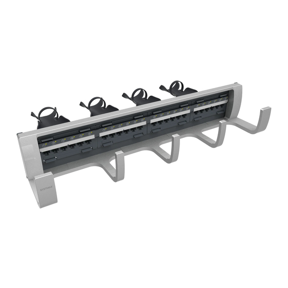
Figure 5 Cabling Modules from the Rear of the Panel
3 After all modules have been cabled, install the rear cable
support, following the instructions in "Installing the Rear Cable
Support (Optional)" on page 5.
Cabling from the Front
To cable modules from the front of the panel:
Important:
Power must be removed from the rack's Panel
Manager when cabling modules for the panel.
1 Install the rear cable support, following the instructions in
"Installing the Rear Cable Support (Optional)" on page 5.
Note: Loosely secure the cable straps so the cables can slide
through the straps during connection.
2 Remove the iPatch sensor overlay from the front of the panel
(Figure 6):
a Slide the overlay to the right to disengage the hooks on the
back of the overlay from the front of the panel.
b Gently lift the overlay away from the panel.
c Disconnect the panel bus jumper from the overlay.
d Set aside the overlay.
For 48-port panels, remove both iPatch sensor
Important:
overlays.
Figure 6 Removing the iPatch Sensor Overlay
Panel bus jumper
3
®
®
PATCHMAX
Modular Panel
Slide the overlay to the
right and then lift it away.