CommScope 360-iP-PMAX-GS5-48 Instruction Sheet - Page 4
Browse online or download pdf Instruction Sheet for Cables and connectors CommScope 360-iP-PMAX-GS5-48. CommScope 360-iP-PMAX-GS5-48 6 pages. Modular panel
3 Select the location where you want to temporarily install the
module to be cabled. Then temporarily remove the module from
the selected location (Figure 7).
Generally it is convenient to remove an adjacent module.
However, Figure 9 illustrates several alternatives for positioning a
module for cabling from the front of the panel.
To remove a 6-pack module
at the top and the 2 tabs at the bottom of the module. Then pull
the module out from the front of the panel.
To remove a 12-pack module
2 tabs at the top of the module. Then pull the module out from
the front of the panel.
Note: If the module you are removing is already cabled, slide the
cables to one side of the opening in the panel to make room for
the module to be cabled.
Figure 7 Removing the Module
6-pack module
Tabs
4 Remove the module to be cabled and temporarily install it
backwards (with the rear facing front) in the vacant panel
opening.
To install a 6-pack module backwards
straight into the panel opening until the module snaps into place.
To install a 12-pack module backwards
of the module into the panel opening so the small tabs hook onto
the edge of the opening (Figure 8). Then gently press the top of
the module until the module snaps into place.
Figure 8 Installing the 12-pack Module Backwards
Small tab
Instruction Sheet: SYSTIMAX 360™ iPatch
, use your fingers to press the 2 tabs
, use your fingers to press the
12-pack module
Tabs
, gently press the module
, position the lower edge
5 Pull the cables through the panel opening where the module will
be installed and mark the cables for termination, leaving an
adequate length of cables to reach the module. Make sure that
the cables can be pushed back into their final position without
interference or snagging.
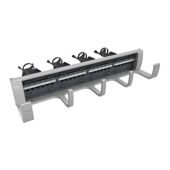
Figure 9 Cabling the Module from the Front of the Panel—Options
in the adjacent panel opening with
cabled modules temporarily removed
6 Cable each module (Figure 9). Use a Termination Manager to
terminate each 4-pair cable, following the Termination Manager
installation instructions provided with the panel. Hold the module
in place with one hand while you punch it down.
Note: The Termination Manager provides pair-twist control and
strain relief features to the rear termination area of the module.
When re-cabling a module, remove each Termination
Important:
Manager by squeezing the lock tabs. Use new Termination
Managers to re-cable the module.
4
®
®
PATCHMAX
Modular Panel
12-pack module
in the adjacent position
6-pack module
in the panel above
6-pack module