CommScope 3X-C70B-3XR Installation Instructions - Page 3
Browse online or download pdf Installation Instructions for Antenna CommScope 3X-C70B-3XR. CommScope 3X-C70B-3XR 4 pages.
CommScope
Bulletin 628043 • Revision A • March 2015 Page 3 of 4
4. Remote Electrical Tilt Connection.
A single AISG 8 Pin DIN Male input connector interface
is provided which will accept a cable assembly
terminated with a standard AISG compliant 8 Pin DIN
Female connector. An AISG 8 Pin DIN Female output
connector interface is also provided which enables a
"daisy" chain connection to other AISG compliant
devices should it be required. After ensuring the
connector is dry, push in the mating connector. Tighten
the AISG mating connector by hand only. Do not apply
any more rotational force to the AISG mating connector
than needed to properly mate the seal and do not
exceed 1.1 Nm. Using excessive torque may damage
the AISG connection in the antenna. If needed or
required by local procedures apply mastic (or similar
waterproofing) to the mating connectors (Figure 4).
Figure 4. Connector Interface.
5.
Attach the RF cables to the antenna input connectors and
torque to 25-30 Nm (Figure 5).
Route RF cable along metal rails, etc. as much as possible,
to enhance noise and lightning immunity. The antenna base
provides openings that can be used to route cable through
the base when mounting on a monopole (Figure 3).
Don't remove female AISG connector cap if it is not used.
AISG 8 Pin DIN
Female
AISG 8 Pin DIN
Male
(Continued from page 2)
RET CABLE
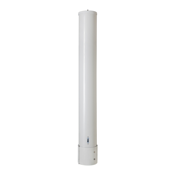
Figure 5. Routing Cables.
(continued on page 4)
Boresite
Indicator
RF CABLE
(X6)