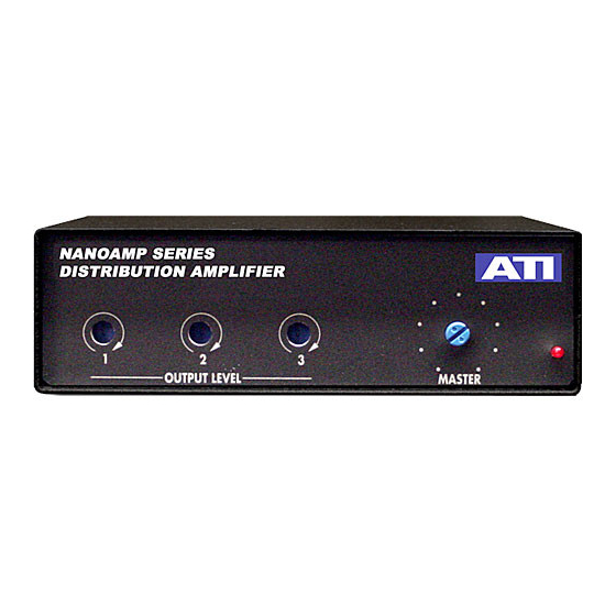
ATI Technologies DA103 Operating And Maintenance Manual - Page 4
Browse online or download pdf Operating And Maintenance Manual for Amplifier ATI Technologies DA103. ATI Technologies DA103 7 pages.

GROUNDING
Operation in high RF broadcast environments requires special attention to
grounding and shielding. The chassis must be grounded directly to a good, low
impedance studio ground system. Input and output connections must be properly
shielded and free of ground loops. It may even be necessary to add shielding to
the DC input leads to avoid RF pickup.
POWER DISTRIBUTION
Multiple NANOAMPS sharing a single wall-wart power supply should be looped
through each other using the DC interconnects cables P/N20602-1. Hum and
noise performance of the units can be degraded by poor DC ground connections
between units sharing a common supply. Use of the recommended rack and
desk mounting kits will assure a good ground connection between units by firmly
strapping their chassis together. CAUTION! The outer shell of the DC
interconnect cables is positive relative to the chassis. Do not allow a DC cable
plugged into a powered unit to hang loose where it can short against the chassis
or rack frame.
SETUP
Before mounting your product in a rack, remove the top cover (4 upper side
screws) and set the preamp gain jumper to match the nominal input line level
(DA103) or for the DMA103 set the preamp gain with the DIP rocker switch to the
highest level that does not cause input circuit clipping. Hot mics will require lower
gains (20 – 30dB) while low output mics will require higher gain settings (40 –
60dB). Also set phantom power on or off as needed and select line (+4dBm) or
mic level (-50dBm) outputs with jumper plugs P1, P2 or P3.
MOUNTING
These may be rack mounted one, two, or three across in a standard EIA 19" rack
and will require only 1 3/4" of vertical space. Rack mount kit P/N20604-501
mounts a single unit, P/N20604-502 mounts two units and P/N20604-503 mounts
three units. Each kit provides a different size pair of rack mounting brackets and
one or two horizontal joiner plates, P/N 20580-1, each with four 4-40 X 5/16" oval
head screws. The joiner plates mount into tapped holes on the bottom of two
side-by-side units, using the supplied screws, while the rack mount brackets
mount under the existing 6-32 cover securing screws on the front sides of the
units.
Audio Technologies Inc. | 154 Cooper Road #902 | West Berlin, NJ 08091 | Voice 856-719-9900 | Fax 856-719-9903 | www.
audio.com
