ATI Technologies SYS10K Operating And Maintenance Manual - Page 3
Browse online or download pdf Operating And Maintenance Manual for Amplifier ATI Technologies SYS10K. ATI Technologies SYS10K 5 pages. Modular amplifier rack system

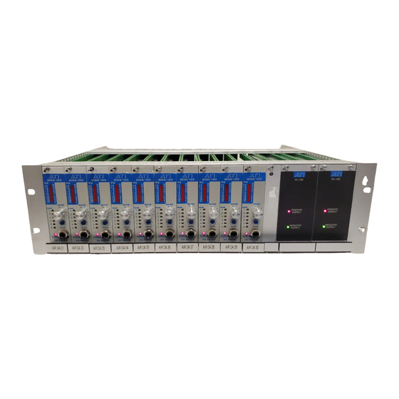
MIDA100-1RC - Remote controllable Distribution Amplifier. Four transformer outputs
each with an independent level trim control. Switchable Remote or Local DC operated
VCA Master Level Control. A LED bargraph meter is switchable to all four outputs or the
input signal. Headphone output.
PS100 - Power Module. A bi-polar unregulated 18 VDC supply drives the system power
buss through fused isolation diodes. Operates singly or as a redundant pair in the right
hand positions of each rack frame. Front panel LEDs indicates low voltage on either
buss or blown fuses. Power Failure Alarm relay contacts close for any power loss and
can activate an external alarm. Alarm outputs from both PS100 positions are paralleled
and brought to a barrier block (pos. 4 & 5) mounted on the left hand rear of the card
cage. Dual power transformers in each module run cooler and generate minimal hum
field. DC lines are fully bypassed. AC line filtering, non-concentric wound power
transformers and varistor clippers prevent power line transient and RF feed thru.
INSTALLATION
MOUNTING A fully loaded RM100 frame is heavy! To protect yourself and the
equipment, mount the empty RM100 enclosure securely before plugging in the power
and amplifier modules. The RM100 is designed for free vertical air convection cooling.
We recommend at least one rack unit (1-3/4 inches) spacing between stacked units or
forced air cooling of more densely stacked frames. If using forced air, seal frames and
joints between frames with duct tape and use blank panels to seal any empty slots to
avoid losing air pressure.
WIRING The RM100 is supplied with mating connectors for the PS100 power supplies
mounted on the right side of the enclosure and with all power busing in place, ready to
plug on to the mating amplifier connector assemblies. Install amplifier modules starting
at the most left hand position (opposite from power supplies) and stack side-by-side for
optimum shielding of each module.
The connector assemblies supplied with each amplifier module mount on the rear of the
rack frame using supplied metric hardware - (4) M 2.5 x 6 mm screws. System audio
inputs and outputs connect to a 15-position barrier block using a supplied mating fanning
strip for easy pre-wiring. The 15-position fanning strip may be cut into smaller sections if
desired, e.g. inputs only, outputs only. The fanning strip is KULKA P/N 649A15 and
replacements are available from ATI stock. Wire the audio inputs and outputs using the
connector assembly markings as a guide. See Fig. 3. NOTE: Barrier block screws are
tightly machine inserted by the manufacturer. Protect your knuckles by loosening them a
few turns before mounting them in a rack where they are hard to reach. Doing so will
make it much easier to install your pre-wired fanning strips at 3 AM. Fanning strips fit
onto barrier blocks from the left.
On special order, connector assemblies with .025 posts instead of the barrier block are
available. These posts mate with AMP MTA100 Series plug-on connectors. The MTA
connectors are solderless insulation displacement types. Special tools for wire insertion
into the MTA connectors include a simple and inexpensive maintenance type tool AMP
Audio Technologies Inc.
Toll Free 800-922-8001
