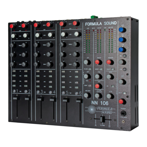
Formula Sound NN106 User Manual - Page 6
Browse online or download pdf User Manual for Mixer Formula Sound NN106. Formula Sound NN106 18 pages. Multi input mixer

Channels 1 & 2 have a balanced stereo line input is on a pair of ¼" 3 pole jack
sockets for input switch position 3.
Channels 3 – 6 have a phono input on RCA phono connectors on input switch
position 3, this phono input has an input capacitance selection switch (4 positions)
and a gain trim accessible through the back panel.
Input 4 is one of the tow USB stereo inputs, the two stereo USB inputs are on a single
USB connector located on the back panel output section, the two stereo USB inputs
are routed to all channels and a recessed switch adjacent to the channel fader allows
USB1 or USB2 (USB stereo channel 1 or USB stereo channel 2) to be selected. Note
there are only two stereo USB channels for the whole mixer, and each channel is may
be set for either of these two.
Each channel has an FX loop switch that sends the signal to the FX LOOP stage in the
output section, and then onto the FX loop jack sockets, if nothing is connected to the jack
sockets the signal is automatically returned to the channel via the FX LOOP stage wet/dry
control. If more than one channel has the FX loop selected then the facility is disabled, this
is because if multiple FX switches are enabled there would be multiple sends and multiple
returns without a disable mechanism so we have included circuitry to sense when more
than one FX switch is selected.
This allows any channel to access a single FX unit connected to the FX jack sockets
by selecting that channels FX switch, only one channel at a time may access the FX
loop and if more than one channel FX switch is selected then the facility is disabled.
An AUX switch sends a copy of the signal at the top of the channel fader to the AUX
output, if several AUX are selected the AUX signals are summed. There is an AUX
output level control in the output section.
The XFA and XFB switches assign the channel signal to a side of the cross fader
(XFA is left and XFB is right), when a channel has microphone selected and the
microphone is assigned to the MIC buss then no mic signal is assigned for that
channel to the cross fader (the MIC buss goes direct to the output).
The CUE switch sends a copy of the signal at the top of the fader to the headphones
in the output section and the CUE meter in the output section indicates the level
providing only one CUE switch is selected (if more then one CUE switch is selected
then the signals are summed and the summed signal level is indicated).
USB input
The USB input is type B connector. The USB input module is an Amanero
Combo384 Module (See
www.amanero.com
website for full specification) operating
up to 192Khz.
