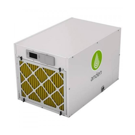
Anden A210V1 Installation And Operating Instructions Manual - Page 4
Browse online or download pdf Installation And Operating Instructions Manual for Dehumidifier Anden A210V1. Anden A210V1 16 pages.
Also for Anden A210V1: Quick Start Manual (4 pages), Quick Start Manual (2 pages)

UNPACKING THE DEHUMIDIFIER
Remove the unit from the carton� Cut the retaining band that secures
the compressor to the shipping bracket and remove the band and the
bracket� See FIGURE 2�
INCLUDED IN THE CARTON
• Dehumidifier
• Installation manual
• Hanging brackets
• Model A77 control
• 3/4" MNPT x 3/4" hose barb fitting
• 10 feet of 3/4" clear PVC flexible drain hose
• Terminal screwdriver
• 30 feet of thermostat cable
• MERV 11 filter
LOCATION CONSIDERATIONS
This appliance is classified as to not be accessible to the general public�
The dehumidifiers should be spaced evenly throughout the area to be
dehumidified with the following recommendations:
1. Avoid placement where the discharge of one dehumidifier is
pointing toward the inlet of another�
2. Avoid locating the dehumidifier inlet too near a supply register�
Space is not usually available to totally avoid this, but minimizing
the amount of cold air that is discharged to the dehumidifier inlet
will improve moisture removal performance of the dehumidifier�
3. Account for handling dehumidifier condensate by considering drain
or sump pump locations�
4. Leave appropriate room on the drain side of the dehumidifier for
wiring and service�
5. Allow 18" minimum clearance near the inlet and outlet of the
dehumidifier� This will allow easier removal/installation of the filter,
as well as ensure no loss of airflow due to restrictions� Clearance of
18" minimum is also recommend on the service panel side of the
dehumidifier, should any maintenance be needed�
FLOOR MOUNTING
The drain hose must continuously slope downward toward the drain� Use solid supports as needed to elevate the unit enough to allow for continuous
drain slope� Use the adjustable feet to level the unit right to left and front to back so that unit drains properly�
4 English
FIGURE 2 – REMOVE SHIPPING BRACKET
FIGURE 3 – SPACE CLEARANCES
18" MIN.
INLET SIDE
REMOVE SCREWS (2)
DISCARD SHIPPING BRACKET
REINSTALL SCREWS (2)
CLIP OFF
AND REMOVE
PLASTIC
STRAP
90-2395
18" MIN.
18" MIN.
SERVICE PANEL
90-2396
