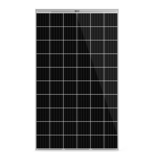
Aleo X63 Installation Manual - Page 10
Browse online or download pdf Installation Manual for Control Unit Aleo X63. Aleo X63 20 pages.
Also for Aleo X63: Installation Manual (20 pages)

9
Electrical installation
9.1 Connectors
WARNING!
Incompatible or unsuitable connectors can overheat: Fire hazard!
Only use connectors that are the same type and from the same
manufacturer.
Avoid using different types of connectors or ones from different
manufacturers, even if:
- connecting is possible,
- the connectors have the same basic designation (e.g.
"MC4") or
- they are designated as "compatible".
You can find more details on this in the next two sections.
9.1.1
Module connectors
The various module types can be fitted with the following connect-
ors:
Original Multicontact® MC4 (with locking)
-
PV-JM601 (with locking).
-
You can find the specific connectors in the module data sheet.
9.1.2
Connector peculiarities
#
Original Multicontact® MC4-connectors:
Only plug original Multicontact® MC4-connectors into original-
Multicontact® MC4-connectors
PV-JM601 connectors:
Only plug PV-JM601 connectors into PV-JM601 connectors.
9.1.3
Replacing the connectors
You can remove the connector on a module and replace it with
another connector, which is released by aleo (see chap. 9.1.2) if
necessary.
You retain the manufacturing warranty if you remove and mount
with approved tools in the proper way and according to the con-
nector manufacturer's instructions.
The original Multicontact® MC4 connectors are referred to as "MC4" in the
2
data sheet.
aleo solar GmbH | Marius-Eriksen-Straße 1 | 17291 Prenzlau | Germany |
,
2
HINWEIS
9.2 Laying the string cables
CAUTION!
Brittle fractures in junction boxes due to contact with unsuitable
connection cables: Risk of fire!
Only use connection cables without plasticisers, certified ac-
cording to the current valid standard.
_________________________________________________
INWEIS
Avoid any tensile and pressure loads on the junction box when
mounting.
When mounting, avoid heavy tensile loads on any connectors
already plugged in.
Bend the cables from the connector at least 4 cm after they exit
from the connector.
Bend the cables from the junction box as well, at least 4 cm
after they exit from the connector.
This keeps the cables waterproof at the cable outlet.
Observe the guidelines on laying the respective cables.
Lay all cables ensuring that:
you adhere to the minimum bend radius (e.g. 5-fold cable
diameter
),
4
you avoid laying near sharp corners and edges or protect
the cables accordingly,
cables must not lay between module backside and
mounting system parts,
you protect them from direct sunlight and precipitation,
you secure the cables with UV resistant cable clips
other suitable cable fasteners which protect the cable in-
sulation,
cables from module strings are laid as near to each other
as possible to minimise the effects of being struck by
lightning.
3
Current standard for solar DC cables in Europe: EN 50618.
4
Some countries specify a larger bend radius, e.g. 8-fold wire diameter in
the USA (NEC Codebook 2011).
For attaching cable clips, use a suitable tool which constrict or damage the
5
cable insulation by tightening.
Installation manual Ver. 4.8, 05/2021, en
3
5
or
Page 10 of 20
