Atkinson Electronics GSCM Operating And Installation Instructions - Page 14
Browse online or download pdf Operating And Installation Instructions for Control Unit Atkinson Electronics GSCM. Atkinson Electronics GSCM 16 pages. Generator start control module
Also for Atkinson Electronics GSCM: Manual (16 pages)

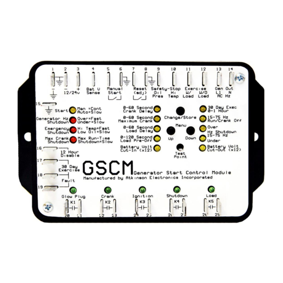
GENERATOR START CONTROL MODULE
GSCM
Engineering Application Bulletin #2 OUTBACK INVERTER AUTO GENERATOR START USING GSCM
The GSCM - Generator auto-Start Control module accepts either as dry contact closer between terminal 5 and 6, or
a 12V DC signal from an Outback inverter's auxiliary output without requiring a separate 12VDC relay as shown in
the Outback Auto Generator Start application. GSCM's with a date code before May 2004 will still require a 12VDC
relay to interface with the Outback inverter. A remote generator start switch or manual off auto switch may still be
connected to the GSCM along with the Outback inverter, but it needs to be connected to the GSCM power terminal
as shown in the optional remote switch diagram. When not connected to the Outback inverter, the remote start switch
may be wired as in Application 1 of the GSCM instructions booklet.
When the start signal is received from the Outback inverter, the GSCM starts the generator with a 3-wire start /stop
or any other generator starting application to match the type of generator to be controlled. If the user desires, the
voltage from the generator's battery may be connected to the GSCM on terminal 4 and the GSCM will start the
generator automatically to charge it's own battery when the voltage falls below the battery cut-in threshold voltage.
The Outback inverter monitors the battery bank, and provides a start signal when the inverter battery bank needs to
be charged. While charging the inverter passes the AC power from the generator to the inverter's loads. If loads
become unbalanced or exceed the rating of generators output harmonics can occur on the generators AC output
causing the GSCM to see an Over Hz condition. If this occurs, it is recommended that an EMI filter be placed in the
AC feedback line (GSCM terminals 13 &14) from the generator (Qualtek Electronics #851-02/001). A second option
is to disable the Over/Under Hz shutdown monitoring and allow the Outback Inverter to monitor the AC for Over/Under
Hz. Condition and shutdown the generator in those conditions.
ATKINSON ELECTRONICS, INC.
REV 8/06
Web Site: www.atkinsonelectronics.com
Distributed by:
