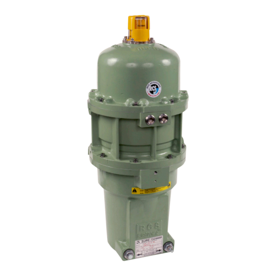
Dresser Surepowr Sure 150 Installation Manual - Page 8
Browse online or download pdf Installation Manual for Controller Dresser Surepowr Sure 150. Dresser Surepowr Sure 150 16 pages. Rcs actuators

Cover Removal and Assembly
Do not open the actuator cover if there is risk of an
explosive environment.
Do not store or set the actuator cover with the flange
surface down. To preserve the explosion-proof integrity
of the joint, care must be taken not to damage, scuff or
score the flange joint surfaces and associated parts (cable
glands, joints, etc.). Take care not to damage the cover
joint when replacing the cover onto the actuator housing.
Ensure that the joint is clean and free of debris or
damage and ensure that the O-ring is intact and in place
before replacing the cover onto the actuator housing.
The explosion-proof joint may be lubricated with an
appropriate, non-corrosive, non-hardening grease, such
as Vaseline.
When replacing the actuator cover, ensure the eight
cover screws are tightened to specified torque value
and that all screws are intact. Failure to maintain specified
screw torque may compromise the enclosure protection
rating.
Under normal operation, the capacitor will discharge
prior to the removal of the cover.
Enclosure cover screw specifications:
Exd or EEx d versions:
8, 10mm x 1.5 x 35 mm,
A4-80 Stainless steel,
apply anti-freeze compound;
torque to 32-33 ft.-lbs. (43-44 N.m)
8
WARNING
EXPLOSION HAZARD –
REMOVE POWER
Death or serious injury
could result.
Do not open unless power to
actuator has been disconnected.
WARNING
EXPLOSIVE ATMOSPHERE
HAZARD
Death or serious injury
could result.
Do not open if an explosive
atmosphere may be present.
WARNING
EXPLOSION HAZARD
Death or serious injury
could result.
Maintain cover screw torque
specifications to avoid hazard.
Mounting
The actuator is shipped in the fail safe position. Ensure
that the driven device is oriented to its desired fail
position prior to installation or any maintenance work
of the actuator.
Care should be taken to maintain proper alignment
between the actuator and the device shaft. The actuator
should install on the shaft without binding. The mounting
face should be centered on the bracket without binding
or side load.
Mount the actuator to the device. Ensure the actuator
is centered properly with the device shaft, and then
tighten all screws and nuts to the mounting fastener
spec. below.
Mounting Fastener Specifications:
4, 3/8"-16 UNC, grade 8 or equivalent,
torqued to 45 in/lbs
Horizontal Mounting
Although the actuator is suitable for mounting in any
orientation, additional support is required at the lifting
lug screw holes for horizontal mounting (Figure 3).
Figure 3
Lifting
Lug Holes
X 4
