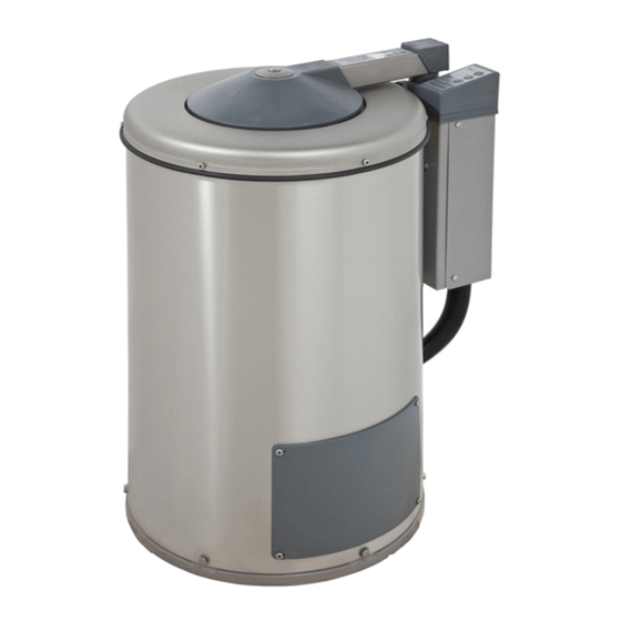
Electrolux C240 Service Manual - Page 26
Browse online or download pdf Service Manual for Ventilation Hood Electrolux C240. Electrolux C240 41 pages. Hydro-extractor
Also for Electrolux C240: Operating Manual (24 pages), Operating And Installation Manual (20 pages)

12
Measurement points
A number of measurement points are shown in the adjacent diagram. The table below
shows what each measurement is for, where to measure and the value which you should
obtain.
The measurements described below should be made with extractor in inactive state, i.e. with
the drum not rotating.
Special care must be taken at the measurement points for the edge connections to the
curcuit bourd for automatic functions. The "measurement covers" for connections must be
opened with no power supply present (Main switch - Off).
Edge connection X16 supplies the primary voltages to the auxilliary transformer, when
measuring S3 and S6 of the Hall element, small thin measuring clips for digital meters must
be used.
Pos. signal
A
Incoming mains voltage.
B
Primary voltage
to aux. transformer.
C
Secondary voltage
from transformer.
D
Power supply, circuit board
Power supply, circuit board
E
Hall element in motor,
power supply.
output**
F*
Reed sensor 1 in lid
Reed sensor 2 in lid
F*
Except C290R
** 0 V DC cannot be measured with an ordinary digital meter during operation.
This potential can be checked with the lid open and by slowly turning the drum clockwise
by hand.
12.14
12. Functions sequences
Measurement
point
X1:L3,L2 and L1
X16: 1-3
X17:1-2
S1: 1-2
S1: 2-3
S4: 3-1
S4: 2-1
S3: 1 GND1 - 2 out 1
S6: 1 GND2 - 2 out 2
Correct value
115V, 200V,
208-240V,
230V, 380V, 400V,
415V or 440V
As above
24V AC
24V AC
24V AC
5V AC
5 V DC
1 rev
0 V DC
Open lid ∞ Ω
Closed lid 0 Ω
Open lid ∞ Ω
Closed lid 0 Ω
Service
manual
487 03 29 91
