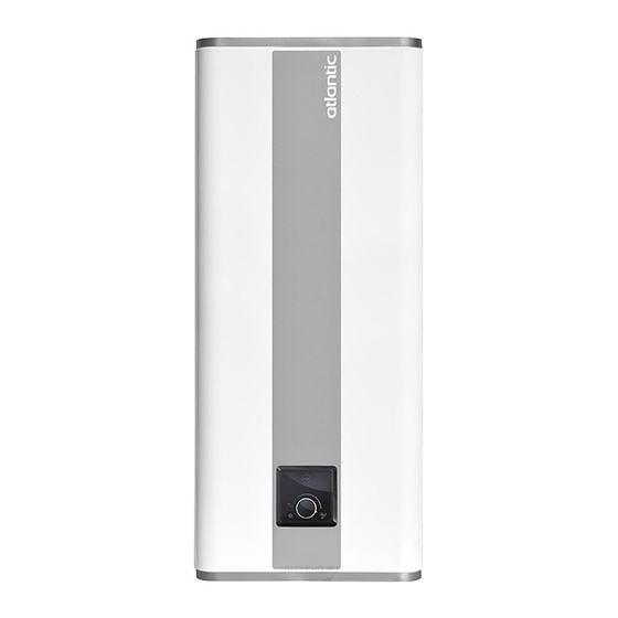
Atlantic Vertigo 30 Installation Manual - Page 5
Browse online or download pdf Installation Manual for Water Heater Atlantic Vertigo 30. Atlantic Vertigo 30 11 pages.

HYDRAULIC INSTALLATION DIAGRAM - VERTICAL & HORIZONTAL
Hydraulic Connection
Before making the hydraulic connection, it is essential to clean the feed pipes thoroughly to avoid the risk of metal
or other particles entering the tank or water heater.
Mandatory installation of a safety TPR valve in a frost free location (or any other new device which limits the tank
pressure) to 850kPa according to the nominal pressure, with a size of ¾" on the input of the water heater,
respecting the local regulations.
Regularly operate the discharge of the TPR valve to prevent scaling and check that it is not blocked.
The pipes used must support MPa (10 bar) and 100˚C.
Cold Water Inlet
Cold water piping should be provided with a 350-500kPa pressure limiting valve at the point of cold water
connection to the water heater. In addition to the pressure limiting valve, it is a requirement of AS3500.4 and
NZBC G12 that both an isolating valve and a line strainer are installed upstream of the water heater. A non-return
relief valve must be fitted upstream of the pressure relief/cold water expansion valve.
No parts (stop valve, pressure reducer, etc) must be placed between the pressure relief/cold water expansion
valve and the cold water inlet of the water heater, apart from a copper pipe. Ref. AS/NZ 3500.4, 5.9.4 (e) and (f)
G12 6.6.6.
Note: Since limited water discharge from the pressure relief valve is normal in the heating operation, the discharge
pipe needs to be connected to an external drain.
5
