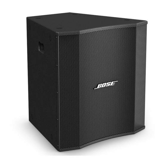
Bose LT 6403 Manual - Page 22
Browse online or download pdf Manual for Speakers Bose LT 6403. Bose LT 6403 35 pages. Lt and mb series loudspeakers
Also for Bose LT 6403: Installation Manual (32 pages), Installation Manual (32 pages), Owner's Manual (32 pages)

1. Woofer Phase Test
1.1 Remove the back panel of the speaker
using the disassembly procedures.
1.2 Disconnect the connectors at the woofer
input terminals. Momentarily apply 8 Vdc + 1
Vdc to the terminals, observing polarity when
connecting the DC P/S. The woofer should
move outward when the DC level is applied.
2. V2 Assembly Drivers Phase Test
2.1 Remove the back panel of the speaker
using the disassembly procedures.
2.1 Disconnect the connectors at the V2
driver assembly input terminals. Momentarily
apply 8 Vdc + 1 Vdc to the terminals, observ-
ing polarity when connecting the DC power
supply. The V2 drivers should move outward
when the DC level is applied.
2. Rub and Tick Test
2.1 Apply a 20 Vrms, 10 Hz signal to the
input terminals of the speaker.
2.2 No extraneous noise such as rubbing,
scraping or ticking should be heard. Ensure
that there is no buzz from the loudspeaker
grille.
3. Low Frequency Power Sweep Test
3.1 Apply an 8 Vrms, 10 Hz signal to the
speaker input terminals.
3.2 Sweep the input frequency from 10 Hz
to 2 kHz.
3.3 Lower the applied input to 3 Vrms, and
sweep the input frequency from 2 kHz to 5
kHz.
3.4 Listen for any buzzes, rattles or other
extraneous noises from the loudspeaker.
Test Procedures
4. High Frequency Power Sweep Test
4.1 Apply a 3 Vrms, 1.0 kHz signal to the
speaker input terminals.
4.2 Sweep the input frequency from 1.0 kHz
to 5 kHz.
4.3 Listen for any buzzes, rattles or other
extraneous noises from the loudspeaker.
5. Passive Operation Rub and Tick Test
Note: This test does not apply to the
LT 6400 or LT 9400 speakers.
5.1 Remove the input panel, and move the
jumpered connector from the BI-AMP to the
PASSIVE position. Re-install the input panel.
5.2 Apply a 20 Vrms, 10 Hz signal to the
speaker input terminals.
5.3 Sweep the input frequency from 10 Hz
to 2 kHz.
5.4 Lower the applied input to 3 Vrms, and
sweep the input frequency from 2 kHz to 5
kHz.
5.5 Listen for any buzzes, rattles or other
extraneous noises from the loudspeaker.
6. Air Leak Test
6.1 Apply a 20 Vrms, 50 Hz signal to the
speaker input terminals.
6.2 Listen for any air leaks around the rear
panel, input panel, waveguide and handles.
Pass any speaker that has no air leaks.
Fail any speaker that has air leaks. All
repairs must not be visible at a distance of
3 feet.
22
