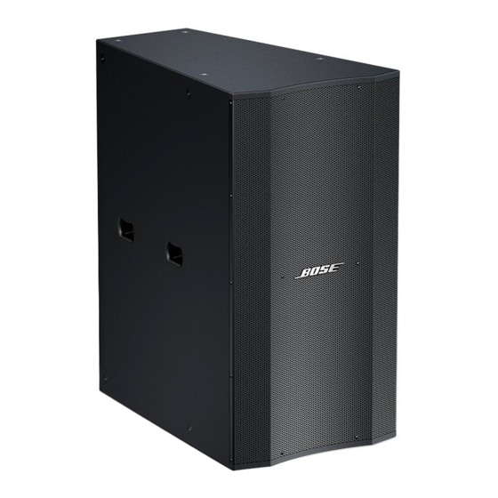
Bose Panaray LT4402 III Mid/High Service Manual - Page 19
Browse online or download pdf Service Manual for Speakers Bose Panaray LT4402 III Mid/High. Bose Panaray LT4402 III Mid/High 27 pages. Panaray lt series iii
Also for Bose Panaray LT4402 III Mid/High: Installation Manual (32 pages), Reference Manual (40 pages)

DISASSEMBLY PROCEDURES
3. Compression Driver Removal
3.1 Remove the twelve screws (13) that
secure the rear panel (12) to the cabinet. Lift
off the rear panel. The gasket should remain
adhered to the cabinet.
3.2 Make a note of the wiring configuration,
and disconnect the wires from the compres-
sion driver. Remove the four screws (9) that
secure the Compression Driver Mounting
Plate (8) to the cabinet. Lift the compression
driver (10) out of the cabinet.
4. VEE Two Assembly Removal
4.1 Remove the four screws that secure the
assembly to the cabinet. These screws are
located at the four corners of the VEE Two
assembly. Do not remove the other screws
around the casting. Carefully lift the assem-
bly out of the cabinet. Make a note of the
wiring configuration, and disconnect the two
wires from the connector.
5. Input Panel Assembly Removal
5.1 Remove the four screws that secure the
input panel assembly to the cabinet. Lift the
assembly away from the cabinet. Be careful
not to damage any wires.
TM
Model 9402
III Loudspeaker
Note: Refer to Figure 9 for the following
procedures.
1. Grille Removal
1.1 Remove the fourteen screws (1) that
secure the grille assembly (3) to the cabinet.
1.2 Lift the grille assembly off of the cabinet.
The gasket should remain adhered to the
cabinet.
2. Logo Removal
2.1 Remove the grille using procedure 1
above.
2.2 On the back of the grille, carefully re-
move the slotted washer that retains the
spring and spacer against the back of the
grille. Note the direction the spacer faces.
Slide the spring and spacer off of the logo
post.
2.3 Lift the logo off of the grille.
3. Compression Driver Removal
3.1 Remove the twelve screws (17) that
secure the rear panel (16) to the cabinet.
Lift off the rear panel. The gasket should
remain adhered to the cabinet.
3.2 Make a note of the wiring configuration,
and disconnect the wires from the compres-
sion driver. Remove the four screws (13)
that secure the Compression Driver Mount-
ing Plate (12) to the cabinet. Lift the com-
pression driver (14) out of the cabinet.
4. VEE Two Assembly Removal
4.1 Remove the four screws that secure the
assembly to the cabinet. These screws are
located at the four corners of the VEE Two
assembly. Do not remove the other screws
around the casting. Carefully lift the assem-
bly out of the cabinet. Make a note of the
wiring configuration, and disconnect the two
wires from the connector.
5. Input Panel Assembly Removal
5.1 Remove the four screws that secure the
input panel assembly to the cabinet. Lift the
assembly away from the cabinet. Be careful
not to damage any wires.
19
