Bose Panaray LT9702 III Mid/High Service Manual - Page 20
Browse online or download pdf Service Manual for Speakers Bose Panaray LT9702 III Mid/High. Bose Panaray LT9702 III Mid/High 27 pages. Panaray lt series iii
Also for Bose Panaray LT9702 III Mid/High: Installation Manual (32 pages), Reference Manual (40 pages)
DISASSEMBLY PROCEDURES
Model 9702
®
III Loudspeaker
Note: Refer to Figure 10 for the following
procedures.
1. Grille Removal
1.1 Remove the fourteen screws (2) that
secure the grille assembly (1) to the cabinet.
1.2 Lift the grille assembly off of the cabinet.
The gasket should remain adhered to the
cabinet.
2. Logo Removal
2.1 Remove the grille using procedure 1
above.
2.2 On the back of the grille, carefully re-
move the slotted washer that retains the
spring and spacer against the back of the
grille. Note the direction the spacer faces.
Slide the spring and spacer off of the logo
post.
2.3 Lift the logo off of the grille.
3. VEE Two Assembly Removal
3.1 Remove the four screws that secure the
assembly to the cabinet. These screws are
located at the four corners of the VEE Two
assembly. Do not remove the other screws
around the casting. Carefully lift the assem-
bly out of the cabinet. Make a note of the
wiring configuration, and disconnect the two
wires from the connector.
4. Input Panel Assembly Removal
4.1 Remove the four screws that secure the
input panel assembly to the cabinet. Discon-
nect the cables that plug into the PCB. Lift
out the assembly.
VEE Two Driver Removal Procedure
1. Remove the VEE Two assembly using the
appropriate disassembly procedures for the
speaker under repair.
2. Place the VEE Two assembly on a flat
surface so that the aluminum casting with
the Bose logo is facing upward.
3. Using a Phillips-head screwdriver, remove
all of the screws around the perimeter of the
casting. Carefully lift off the casting. The
drivers will be exposed.
4. Make a note of the wiring configuration,
and cut the wires as close to the terminals
as possible.
5. Remove the three screws that secure the
driver into the housing. Lift it out of the
housing.
Re-assembly note: When installing the
new driver, ensure that the gasket for the
driver and the gasket for the aluminum
casting are correctly positioned to provide
an airtight seal after re-assembly.
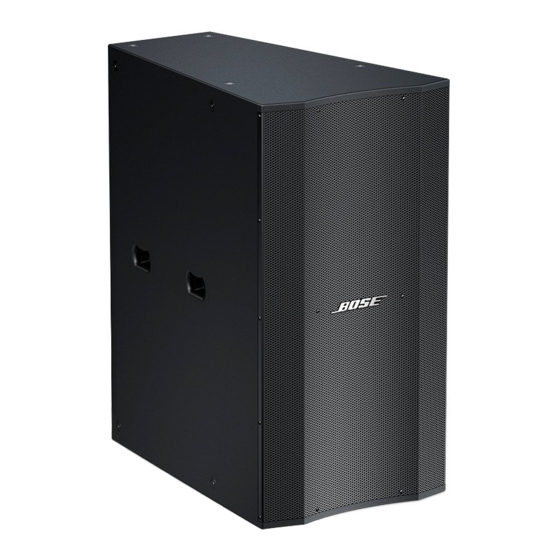
Model MB24 and MB12 III Bass Loud-
speakers
Refer to Figure 11 or 12, as appropriate,
for the following procedures.
1. Grille Removal
1.1 Using a Phillips-head screwdriver, re-
move the screws that secure the grille to the
enclosure. Lift off the grille.
2. Driver Removal
2.1 Perform procedure 1 above.
2.2 Using a Phillips-head screwdriver, re-
move the 8 screws that secure the driver to
the enclosure.
2.3 Lift the driver out of the enclosure. Make
a note of the wiring configuration and cut the
wires as close to the terminals as possible.
Re-assembly Note: Be sure that the driver
gasket is properly aligned to provide an
airtight seal. If the gasket is damaged, use a
new one.
20