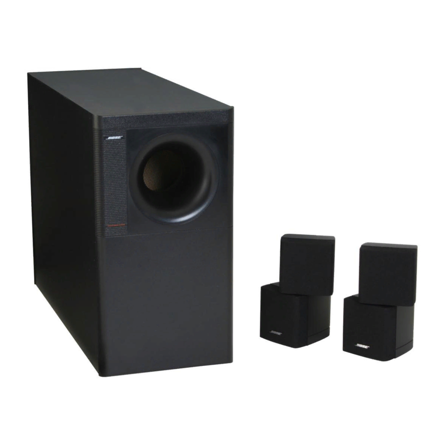
Bose 21725 Owner's Manual - Page 7
Browse online or download pdf Owner's Manual for Speaker System Bose 21725. Bose 21725 16 pages. Bose acoustimass 5 series iii speaker system owner's guide

- 1. Selecting the Locations for Your Acoustimass System Components
- 2. Examining the Cables and Connections
- 3. Connecting the Cube Arrays to the Acoustimass Module
- 4. Connecting the Acoustimass 5 Series III System to Your Receiver
- 5. Positioning Your Speaker System to Get the Best Sound
- 6. Technical Information
2. Selecting the locations for your Acoustimass
Figure 2
Acoustimass module positions
3. Examining the cables and connections
AM196451_05_V.pdf
1. You can place the Acoustimass module almost anywhere in your listening room, in either
a vertical or horizontal position (Figure 2). It can be hidden under a bed or table or even
behind a sofa, as long as you remember not to block the round opening in the end of the
unit. Allow at least 2 inches (5 cm) of space between that end and any surface. After
selecting a place for the Acoustimass module, attach the four rubber feet to the bottom
surface for additional stability. If you choose to stand the module on its connection end,
the feet must be attached to protect the wire connections.
CAUTION: The Acoustimass module is not magnetically shielded and should be kept at
least two feet (.6 m) from a television.
2. Next, select the positions for the left and right cube arrays. Remember that wires from the
arrays connect to the Acoustimass module, so you should locate the cube arrays close
enough to the module to enable the wires to reach it. The cube arrays are magnetically
shielded, so they may be placed near a television.
Note: Bose
®
wall brackets and floor stands can increase your placement options. See page
12 for details and ordering information.
Note: While the wires provided are adequate for most installations, you may increase the
distance between the cube arrays and the Acoustimass module by splicing in additional
wire. If you do so, use similar gauge or thicker wire, and make sure you maintain the correct
phase (+ to + and – to –), and properly connect the wires.
Locate the four identical pairs of wires packed with the system.
• Two wire pairs connect your cube arrays to the Acoustimass module.
• The other two wire pairs connect the Acoustimass module to your receiver or amplifier.
• Examine the ends of the wires. The marked wire (with a red, striped, or printed marker)
connects to the positive (+) terminal at each connection.
• The cube arrays and the Acoustimass module have red positive (+) connections.
October 23, 2001
Setting Up
®
system components
5
