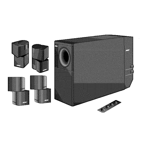
Bose Acoustimass 5 Owner's Manual - Page 11
Browse online or download pdf Owner's Manual for Speaker System Bose Acoustimass 5. Bose Acoustimass 5 22 pages. Powered speaker system
Also for Bose Acoustimass 5: Owner's Manual (9 pages), Owner's Manual (22 pages), Owner's Manual (16 pages)

Connecting
the Acoustimass
module
to multi.room
interface
systems
Figure
11
Connecting me speakers to
your multi room interface
®
©
.VAR
Ak
Note:
To extend the length of the cables, use the supplied 50-foot extension cable (shown
in the dotted line above). This cable connects between the 30-foot audio input cable and the
3-foot VAR adapter cable.
To connect the Acoustimass 5 or 20 powered speakers to your system, follow these steps:
1. Using the supplied 30-foot audio input cable, insert the round DIN connector into the
Acoustimass module, and the RCA plugs into the supplied 3-foot VAR adapter cable
labeled VAR on the single-connector end.
2. Attach the single-connector end of the 3-foot VAR adapter cable to one of the unused
ROOM output jacks (B, C, D) on the rear of the multi-room interface (Figure 11).
Connecting
power
to your
system
CA UTION
If you purchased a dual-voltage system, it is important that you set the speakers
to the correct voltage. To do this, refer to "Selecting the correct voltage" on page 6.
Follow these steps to connect power to your Acoustimass powered speaker system:
1. Plug the power cord from the Acoustimass module into an AC power (mains) outlet.
2. Insert the power cord of the Lifestyle' system into an AC power (mains) outlet.
3. Turn the Acoustimass module power switch to the On position.
Operating
in more
than
one
room
Your Lifestyle' system Personal' music center can control up to four sets of Bose powered
speakers, allowing your family to enjoy four different audio sources (CD, radio, TV, etc.) in up
to four rooms. These rooms are referred to as room A, B, C, and D, with room A being the
primary room (the one used for a one-room system). If two or more rooms are connected to
your system, the Personal music center displays ROOM and HOUSE buttons, and room
indicators (A, B, C, and/or D). Figure 12 shows a sample display for a two-room system.
Note_o
not plug the AC power pack into a power Outlet until all Component Connections
are complete.
AM26283S
O0 !Zpdf
December 20, 2001
9
