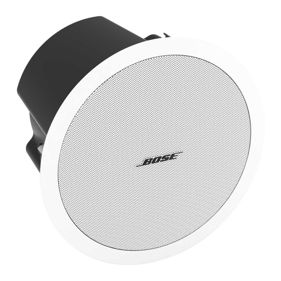
Bose FreeSpace DS 100SE Service Manual - Page 16
Browse online or download pdf Service Manual for Speaker System Bose FreeSpace DS 100SE. Bose FreeSpace DS 100SE 21 pages. With ceiling mount bracket
Also for Bose FreeSpace DS 100SE: Owner's Manual (32 pages), Installation Manual (17 pages), Technical Data Sheet (8 pages), Installation Manual (22 pages), Design Manual (4 pages)

DISASSEMBLY PROCEDURES
5. Rear Enclosure Removal
5.1 Perform procedure 1.
5.2 Using a Phillips-head screwdriver, re-
move the five screws (22) located around the
perimeter of the loudspeaker's front baffle.
Remove the one screw (22) located on the
side of the rear enclosure near the woofer.
Slide off the rear enclosure.
6. Crossover PCB Removal
6.1 Using a Phillips-head screwdriver, re-
move the five screws (22) located around the
perimeter of the loudspeaker's front baffle.
Remove the one screw (22) located on the
side of the rear enclosure near the woofer.
6.2 Disconnect the two Faston connectors
from the woofer terminal strip (14). Discon-
nect the two Faston connectors from the P1
and P2 pins on the crossover PCB (9).
6.3 Perform procedure 1.
6.4 Using a Phillips-head screwdriver, re-
move the four screws (24) that secure the
tweeter to the front baffle (8). Lift out the
tweeter. Disconnect the two Faston connec-
tors from the tweeter terminals. Remove the
foam batting and feed the wires out through
the hole in the tweeter enclosure.
6.5 Remove the four screws that
secure the crossover PCB assembly to the
enclosure. Lift off the PCB assembly.
7. TAP Rotary Switch Removal
7.1 Perform procedure 5.
7.2 Using a small flat-tip screwdriver, gently
pry underneath the TAP switch knob (5) to
remove it. Take care to not mark the enclo-
sure or baffle.
7.3 Using a nut driver, remove the nut that
secures the switch (10) to the baffle. Slide
the switch out of the baffle.
8. Audio Transformer Removal
8.1 Perform procedure 7.
8.2 Make a note of the wiring configuration
of the transformer harness wiring connec-
tions. Unplug the two Faston connectors
from the crossover board at P1 and P2.
Unplug the three Faston connectors from
the terminal board located on the rear
enclosure.
8.3 Remove the four screws (24) that
secure the audio transformer (12) to the
enclosure. Lift out the transformer.
16
