Bose FreeSpace 6 Installer's Manual - Page 23
Browse online or download pdf Installer's Manual for Media Converter Bose FreeSpace 6. Bose FreeSpace 6 39 pages. Business music system
Also for Bose FreeSpace 6: Installer's Manual (16 pages), Technical Specifications (2 pages)

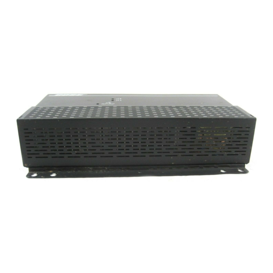
2.9 Mounting system electronics
The system electronics can be shelf or wall mounted. If wall mounted, use proper attachment techniques for your
wall construction type.
3
/
"
1
2
(89 mm)
2.9.1 Wall mounting
WARNING
Do not use the system electronics as a drill guide; personal injury could result. Be sure to observe all other safety
precautions while drilling or installing the mounting hardware.
Attach the system electronics to a vertical surface using at least four of the ten mounting holes. In the U.S., #10 sheet
metal or machine screws, or
"keyhole" mounting holes.
The type and length of fastener depends upon the mounting surface selected. To mount to hollow gypsum board or
plaster wall, use wall anchors with a load rating in shear of at least 25 pounds PER FASTENER. Direct attachment to
more substantial material also should meet this criteria. The keyholes make it easy to pre-install the fasteners before
mounting. For security from accidental or rapid removal of the system electronics, use washers under the screw
heads. This prevents using the keyhole feature. The two additional round holes may be used for the same purpose.
Recommendation: Bose
additional holes allow you to mount the system electronics securely.
2.9.2 Shelf mounting
1. If mounting in an audio equipment rack, use a shelf designed for rack systems. If the shelf is above other sources
of heat such as amplifiers, use a solid material shelf not a perforated material shelf.
Note: DO NOT attach a rack panel to the front of the system box to mount it in a rack.
2. Maintain the 2 inch (50 mm) clearance recommendations when stacking electronic equipment above or below
the system electronics.
3. To prevent accidental dislodging of the system box, use at least two mounting screws to attach the system to
the shelf surface.
4. Use cable ties or other forms of strain relief on the signal and loudspeaker cables to prevent excessive mechani-
cal stress on the wire connections.
5. Allow enough cable slack to move the system electronics forward if adjusting the controls is needed.
6. Dress the wiring so that no one can accidentally trip over it.
7
/
"
3
4
197 mm
10
/
"
5
8
(270 mm)
13"
(330 mm)
3
/
inch diameter wood screws (or 4 mm diameter metric screws) will work with the
16
®
recommends using at least one fastener at each of the four corners of the product. The
AM180090_02_V.pdf • May 7, 2002
2.0 Installation
9
/
"
1
2
241 mm
8
/
"
1
2
217 mm
23
