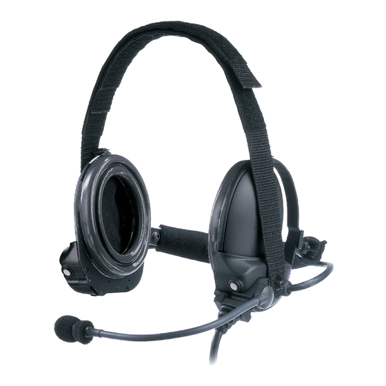
Bose TriPort TTH 2 Manual, Operating & Maintenance - Page 23
Browse online or download pdf Manual, Operating & Maintenance for Headsets Bose TriPort TTH 2. Bose TriPort TTH 2 25 pages. Tactical headsets

Framingham, MA 01701-9168
PTT Switch
The PTT switch shall provide the following function at the vehicle interface
connector:
Switch Position
Up, latching
Center, latching
Down, momentary
The boom microphone output signal shall not be muted or disconnected from the
vehicle interface connector in any PTT mode. The vehicle interface connector
shall conform to the pinouts described in Section 3.0 of this document.
Input Impedance
The headset shall not cause damage to the intercom audio circuits under any
circumstances. The audio input impedance of the headset assembly shall be as
follows:
Power Mode
Intercom and Low Power
Unpowered
Insulation resistance
The insulation resistance of the headset assembly between any interconnection
terminals and any exposed metal cover shall not be less than 10 Megaohms.
Dielectric withstanding voltage
The headset assembly shall withstand, without flashover or breakdown, the
application of a 100Vrms alternating potential of commercial line frequency for 10
seconds.
Crosstalk
The headset assembly shall provide at least 60dB of separation between the
transmit (mic) and the receive (audio input) as well as the transmit (mic) and
power lines.
SIZE
FSCM
A
32108
Function
PTT line (contact #2) connected to ground
(contact #3) through 470±5% ohms (power
dissipation in this resistor is less than 0.1W)
PTT line (contact #2) open circuit
PTT line (contact #2) connected to ground
(contact #3) through 10 ohms maximum
Audio Input Impedance
500 ± 10% ohms
No less than 10 ohms
CLASS
DWG NO.
RF
273139
SHEET
REV.
23 of 25
01D
