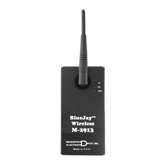
BECKWITH ELECTRIC BlueJay M-2913 Manual - Page 4
Browse online or download pdf Manual for Transceiver BECKWITH ELECTRIC BlueJay M-2913. BECKWITH ELECTRIC BlueJay M-2913 10 pages. Wireless data transceiver

M-2913 BlueJay Wireless Data Transceiver
Typical Connections Guide
The M-2913 can be applied in one of two methods.
1.
Point-to-Point Configuration: Between an M-2913 and an M-2911, with the M-2913 connected
to a host computer running Windows™ 98-SE or later, and the M-2911 connected to a PC,
modem, or another IED.
Detailed elements of a typical Point-to-Point configuration are as follows:
a. One M-2913 is connected to a PC USB port using a typical USB cable.
b. The second M-2913 is connected to the RS-232 port of a M-2667 Autodaptive
Control using an RS-232 straight through cable and gender changer.
Communications can now be established between the PC and M-2667 as if they were directly
connected. In this example, if the SLIMcom Communications Software were to be used, the
software should detect that the M-2913 is connected to the PC, and then prompt the user for an
address.
2.
Point-to-Multipoint Configuration (also known as Master/Slave): In the Point-to-Multipoint
configuration, one M-2913 is configured as the Master unit with multiple-connected IED units
configured as Slaves (see AT Commands in the M-2911 Specifications for Master/Slave setup).
This configuration may be used where, for example, the Master unit is located in a control house
and the slaves are spread out throughout a substation yard.
Detailed elements of a typical Point to Multipoint configuration are as follows:
a. One M-2913 (Master) is connected to the USB port of the host computer. It is configured as
a master unit.
b. Nine IEDs are located throughout a substation yard, each with an M-2911 connected to it
using a straight through RS-232 cable connected to the IED COM Port.
Each M-2911 is configured as a Slave unit. (See the Addressing section under AT
commands in the M-2911 Specification Guide for details.)
c. At a remote location, an RTU has been configured to dial the modem located at the control
house and poll each unit at the substation at 5 minute intervals. For this application to
operate successfully, the RTU cannot poll all units simultaneously.
Optimal Antenna Configuration
A variety of antenna types can be used with the M-2913. The antennas available from Beckwith Electric are
FCC qualified for use with our product. Use of an antenna not supplied by Beckwith Electric could violate
FCC licensing and result in fines to the user. All antenna types currently offered are considered omnidirec-
tional antennas. An omnidirectional antenna is so named because it is designed to radiate equally in all
directions horizontal to the antenna. These antennas have been designed to radiate in a horizontal pattern,
which is best approximated by a toroid, or "doughnut" illustrated in Figure 7. This is also why most
omnidirectional antennas are rated to have a three dB gain over a true spherical radiator. The antenna
appears to have a power gain of two times (3 dB), compared to a true spherical radiator.
Optimum performance of Beckwith Electric-supplied antennas is obtained when the main axis of the antenna
is located perpendicular to the Earth's surface. This allows the toroidal pattern to radiate the maximum range
in each dimension. When the RF energy of the radiation pattern contacts ground, or a grounded surface, it is
absorbed in varying degrees depending on the conductivity of the surface. It is important to have a clear
view, or "line-of-sight" between antennas as illustrated in Figure 8. Any obstructions between the antennas
can absorb some energy, and can reduce the range of operation. Also, if a grounded plane is located parallel
to and close to the antenna, such as a wall located next to the antenna, it can change the impedance match
between the antenna and free-space. This condition can severely reduce the range that can be normally
obtained in unblocked directions. A rule of thumb is to ensure that any grounded objects are kept at least 10
wavelengths (50 inches for 2.4 GHz) away from the antenna in the plane of radiation (Figure 8). 50 inches is
only a guideline, and may be shortened if extreme range is not required. Some experimentation with antenna
location will be needed to optimally set up wireless in a substation environment.
–4–
®
Tapchanger
