3M 701 Operator's Manual - Page 2
Browse online or download pdf Operator's Manual for Measuring Instruments 3M 701. 3M 701 8 pages. Megohmmeter
Also for 3M 701: Calibration Procedure (7 pages), Operator's Manual (9 pages)

INTENDED USE
The 3M Model 701 Megohmmeter is designed to measure
the resistance of static control work surfaces and flooring.
This is to be done in a manner as described in this operator's
manual. Measurements described in this manual refer to the
ESD Association Standards S4.1 (Worksurfaces-Resistive
Characterization) and S7.1 (Floor Materials-Resistive
Characterization of Materials). These standards are
available from the ESD Association (315-339-6937).
Refer to the operator's manual for complete use of this
instrument. Use of other components may cause improper
performance and or an unsafe condition.
SAFETY SYMBOLS
This marking adjacent to another marking
or a terminal or operating device
indicates that the operator must refer to
an explanation in the Operating
Instructions to avoid damage to the
equipment and/or personal injury.
WARNING: Indicates a potentially
hazardous situation which, if not avoided,
could result in death or serious injury.
CAUTION: Indicates a potentially
hazardous situation which, if not avoided,
may result in minor or moderate injury. It
also may be used to alert against unsafe
practices that may cause property
damage.
SAFETY INFORMATION
The Operator's Manual contains cautions and warnings
alerting the user to hazardous operating and servicing
conditions. This information is flagged by CAUTION or
WARNING headings throughout this publication, where
applicable, and is defined in this manual under SAFETY
SYMBOLS. To ensure the safety of operating and servicing
personnel and to retain the operating integrity of this
Instrument, these instructions must be adhered to.
• Turn off the Instrument before connecting or
disconnecting test leads, or before moving test weights.
• Do not use this Instrument with any accessories not
specifically designed to be used with this product.
• Do not use this Instrument to measure live circuits.
• The circuitry enclosed in the Model 701 produces high
voltages. Make sure that the main selector switch is in
the OFF position before removing the back cover.
• Product intended for indoor use only.
• The test weights included in this kit are heavy. Exercise
care in handling.
• Improper battery installation will damage this
instrument.
INTRODUCTION
DESCRIPTION
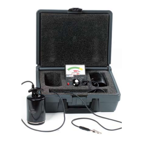
The Model 701 Test Kit for Static Control Surfaces includes
a hand-held megohmmeter (here-in after referred to as the
"Instrument" or "Model 701") and accessories. The kit has
been specifically designed for evaluating the resistive
characteristics of static control surface materials and testing
installed surfaces as specified in ESD Association Standards.
The Instrument has four test functions which allow the user
to measure the resistance of a static control surface at either
of two test voltages, verify proper Instrument performance,
and check the electrical continuity of the test set-up.
ACCESSORIES
All accessories required for operating the Model 701 are
included in the test kit. Available replacement parts are
listed on page 6.
UNPACKING AND INSPECTION
Examine the shipping carton for obvious signs of damage.
If damage is suspected, open the carton and inspect the
Instrument for possible damage. If damage is noted, notify
the carrier and supplier immediately. If the Instrument
appears to be in good condition, read this Operator's Manual
in its entirety. Check that all items are included with the Kit,
then run a series of familiarity tests as instructed in this
manual.
CONTROLS, CONNECTORS,
AND INDICATORS
GENERAL
Before attempting any operation of the Instrument, become
familiar with each control. A thorough understanding of
how the Instrument operates will avoid undue mistakes and
prolong its useful life.
Figure 3-1. Controls, Connectors, and
Indicators
1. Main Selector Switch:
Main function selector switch allows selection of desired test
function.
2. TEST Button:
This button engages the Instrument and activates the test function
selected.
3. OHMS Scale:
This scale is used in conjunction with the SURFACE TEST functions
to indicate the amount of resistance measured.
4. CONTINUITY Scale:
This scale indicates the total resistance of the test set-up (meter,
leads, weights, and calibration plate) in the CONTINUITY TEST
function.
5. BATTERY Scale:
This scale indicates the charge level of the main battery of the
Instrument in the BATTERY TEST function by verifying the open
circuit output test voltage.
6. Test Jacks:
These jacks are used to connect the Instrument to the test leads.
1
