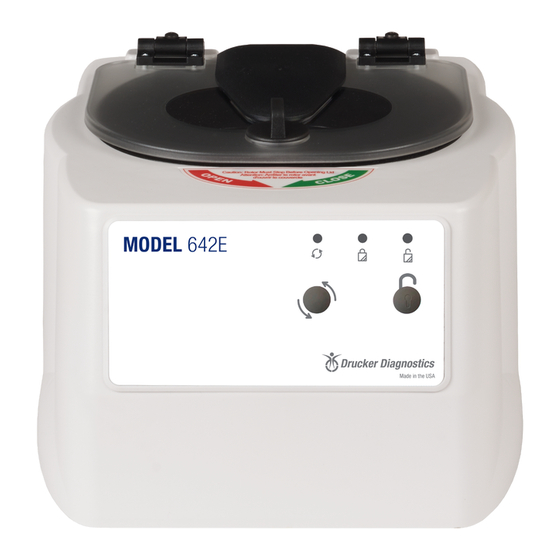
Drucker Diagnostics 642E Service Manual - Page 6
Browse online or download pdf Service Manual for Laboratory Equipment Drucker Diagnostics 642E. Drucker Diagnostics 642E 16 pages.
Also for Drucker Diagnostics 642E: Operator's Manual (8 pages)

b) All Drucker centrifuges currently manufactured are classified as "laboratory equipment",
per the requirements of UL 61010-1 Electrical Equipment for Measurement, Control and
Laboratory Use; Part 1: General Requirements. This standard specifies that the
maximum current levels between any accessible parts are as follows:
c) In normal condition the maximum current flow between accessible parts is 0.5mA RMS
for sinusoidal waveforms, 0.7mA peak for non-sinusoidal waveforms or mixed
frequencies, or 2mA DC.
d) In single fault condition the maximum current flow between accessible parts is 3.5mA
RMS for sinusoidal waveforms, 5mA peak for non-sinusoidal waveforms or mixed
frequencies, or 15mA DC.
6.7
Ground continuity
a) Check the centrifuge's ground continuity periodically, we recommend every two years.
b) Disconnect the manufacturer's supplied power cord from the power supply.
c) Measure the resistance between the ground tab of the line cord and an exposed, clean,
unpainted metal surface contiguous to the chassis main frame.
d) The maximum acceptable ground resistance is 0.1 Ohms.
6.8
Removing the Cabinet (Upper Housing)
a) There are six screws that fasten the centrifuge cabinet to the base.
b) Begin by unplugging the centrifuge, and waiting 10 minutes for internal voltages to
dissipate.
c) Use a #2 Phillips screwdriver to remove the cabinet screws (two on left and right sides,
two in the rear)
d) The centrifuge control panel is attached to the base internally with cable harnesses. Be
careful not to stress the cables when removing the cabinet.
e) Stand directly in front of the centrifuge and lift the cabinet straight up and off the base,
setting it down on its right side.
f) Gently remove the combination power supply / motor harness from the PCB.
6.9
Replacing the Lid Tray Assembly
a) The lid tray assembly is accessible once the cabinet has been removed.
b) Gently remove the lid tray wire harness from the PCB.
c) The lid tray assembly is held in place with two #6 Nylok nuts. Use a 5/16" nut driver to
remove the nuts. The tray will slide off the threaded studs.
d) Early models used a plastic spacer between the tray assembly and the metal cabinet. A
spacer is no longer needed. IMPORTANT: Remove any plastic spacer that may be
present.
DRUCKER DIAGNOSTICS
MODEL 642E SERVICE MANUAL
SM006
REV: A
6
