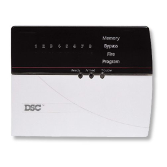
DSC PC5108L Installation Manual - Page 4
Browse online or download pdf Installation Manual for Security System DSC PC5108L. DSC PC5108L 17 pages.

S
2.1 Unpacking the PC5108L
The PC5108L product should include the following items:
• one PC5108L module
• five plastic stand-offs
2.2 Mounting the Unit
The PC5108L should be located inside a compatible metal cabinet,
mounted in a dry, secure location. Preferably, it should be placed
close to the control panel and at a convenient distance from the
connected devices.
Perform the following steps to mount the unit:
1. Press the four plastic stand-offs through the circuit board
mounting holes at back of the cabinet.
2. Secure the cabinet to the wall in the desired location. Use
appropriate wall anchors when securing the cabinet to drywall,
plaster, concrete, brick or other surfaces.
3. Press the PC5108L board into the four plastic stand-offs to
secure the module to the cabinet.
Once the unit is mounted, wiring may be completed.
2.3 Wiring the Unit
Before beginning to wire the unit, ensure that the power (AC trans-
former and battery) is disconnected from the control panel.
Perform the following steps to complete wiring:
1. Connect the four Keybus wires to the PC5108L. Connect the red,
black, yellow and green Keybus wires to the RED, BLK, YEL and
GRN terminals, respectively.
2. Connect the DLM-4L module (if used) to the PC5108L. A 75 ohm
coaxial cable is required for this connection. For more
information, see the DLM-4L Installation Instructions.
3. Connect the cameras to the PC5108L using RG-59 75 ohm
coaxial cable.
4. Connect the external tamper switch to the PC5108L, if used. If
not used, run a wire from TAMP to any COM terminal.
5. Complete all zone wiring to the PC5108L. Refer to the PC5015
Installation Manual for information on zone wiring configurations.
Installation
E
C
T
I
O
2
N
2
