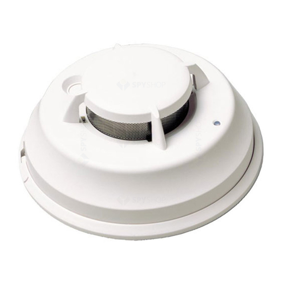
DSC FSB-210B Installation And Operation Instructions
Browse online or download pdf Installation And Operation Instructions for Smoke Alarm DSC FSB-210B. DSC FSB-210B 4 pages. Fsb-210 series smoke detector

Read this instruction sheet thoroughly before installation and use of the FSB-210 Series Smoke Detector
This Installation Sheet must be used in conjunction with the appropriate Alarm Controller Installation Manual.
Control Panel Compatibility
FSB-210 smoke detectors are addressable system detec-
tors that are only for use with DSC fire and security con-
trol panels equipped with the compatible interface. The
FSB-210 smoke detectors cannot be used with a standard
2-wire smoke detector interface. Any standard 2-wire
smoke detector, including the DSC FSA Series, will not
operate on an addressable circuit. The FSB-210 series and
the FSA Series are not compatible, interchangeable or
substitutable.
The addressable interfaces have a proprietary power and
signaling system. Voltage ratings are not indicative of
compatibility. The current rating is provided for circuit
loading calculations only. Please refer to the control panel
information for details on the installation of addressable
circuits.
FSB-210 detectors are compatible with the following con-
trol units:
• PC5010/PC5015/PC5020/PC5020CF v2.x with PC5100
interface module. Maximum 32 detectors can be
installed.
• PC4010/PC4010CF/PC4020/PC4020CF v3.x. Maximum
112 detectors can be installed.
Operation
Approximately every 7 to 8 seconds the unit tests for a
smoke or heat alarm condition. During this sequence the
unit also performs self diagnostics, and checks for faults.
During normal operation the LED will flash every 50 seconds.
Smoke Alarm
The smoke detector has a nominal fixed alarm sensitivity
(refer to the Specifications section on the back page) and
it will go into alarm when the signal level exceeds the
FSB-210 Series Smoke Detector
Installation and Operating Instructions
LED
Place magnet here
Alignment Marks
'alarm' threshold and send the alarm signal to the control
panel. During an alarm the LED will flash every second.
Smoke - Drift Compensation
The detector automatically compensates for long-term
environmentally induced changes to maintain a constant
smoke sensitivity. When the drift compensation has
reached its high or low limit of adjustment, the detector
will go into the trouble state.
Heat Alarm
The heat detector will go into alarm when the heat signal
level exceeds the heat alarm threshold (135ºF/57ºC); and
send the alarm signal to the control panel. During an
alarm the LED will flash every second.
Alarm Indications
Condition
Normal/Sensitivity in Production Range
Alarm Smoke/Heat
Low Power Trouble
Other Fault/Trouble
Smoke Test - Failed
Installer Instructions
1. Smoke Detector Placement
On smooth ceilings, detectors
may be spaced 9.1m (30ft)
apart as a guide. Other spac-
ing may be required depend-
ing on ceiling height, air
movement, the presence of
joists, uninsulated ceilings,
etc. Consult National Fire
Alarm Code NFPA 72, Chap-
ter 11 or other appropriate
national standards for instal-
lation recommendations.
• Do NOT locate smoke detectors at the top of peaked or
gabled ceilings; the dead air space in these locations may
prevent the unit from detecting smoke. Avoid areas with
turbulent air flow, (near doors, fans or windows). Rapid
air movement around the detector may prevent smoke
from entering the unit.
• Do NOT locate detectors in areas of high humidity.
• Do NOT locate detectors in areas where the temperature
rises above 38ºC (100ºF) or falls below 5ºC (41ºF).
LED
Flash 1/50s
Flash 1/1s
OFF
OFF
OFF
