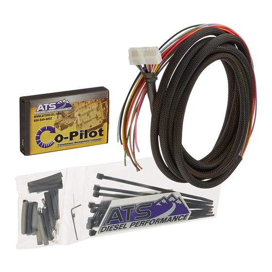
ATS Co-Pilot Installation Manual - Page 11
Browse online or download pdf Installation Manual for Automobile Accessories ATS Co-Pilot. ATS Co-Pilot 15 pages. For dodge cummins 2003
Also for ATS Co-Pilot: Installation Manual (12 pages), Installation Manual (12 pages)

Reasons for use: Preventing trouble codes
Where to connect it: At the dark green with yellow tracer wire in the 6-Pin connector that is
located at the transmission range sensor, driver's side of transmission, near the pan rail.
How to connect it: Strip back approximately ½" of the insulation from the dark green with
yellow tracer wire and solder the Co-Pilot's tan wire to the dark green with yellow. Protect this
connection.
BROWN (PIN #6) AND PURPLE (PIN #16) WIRES ARE NOT USED IN THIS
INSTALLATION.
-Gray Wire- Exhaust Brake (Vehicles with exhaust brake only) – PIN #13
If you do not have an exhaust brake, skip this section.
Reason for use: This function allows your aftermarket or factory exhaust brake to turn on with
the Co-Pilot torque converters lockup when decelerating only. OPTIONAL
If you do not have an exhaust brake, leave the Grey wire unconnected.
