DSM SUM-40 Operating Manual - Page 6
Browse online or download pdf Operating Manual for Measuring Instruments DSM SUM-40. DSM SUM-40 6 pages.
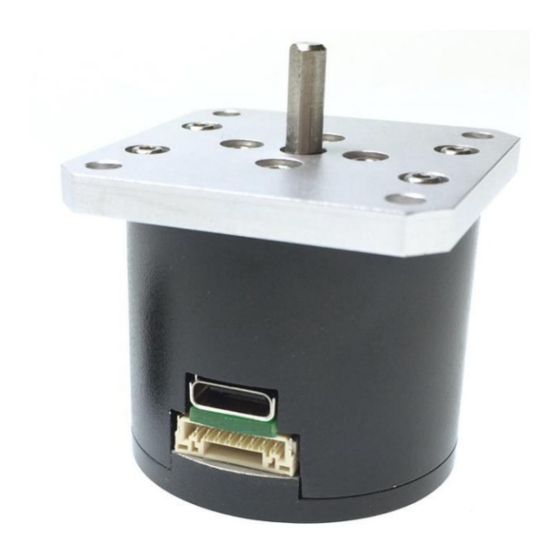
The multi-function connector on the SUM-40 mates with a GHR-08V-S connector. DSM
includes one such connector with flying lead wires with the purchase of each SUM-40 motor.
The pinout of this connector is given below.
Pin number Color
1,2
Red
3,4
Black
5
Blue
6
Purple
7
Orange
8
Yellow
Pin 1
Pin 8
On the GHR-08V-S connector, the pins are numbered such that with the disconnect tab facing
UP, pin number 1 is on the far LEFT of the connector.
For more information on communicating with the SUM-40, refer to the "SUM-40
Communication Protocol" document. That document includes command methods and specific
commands used to control the SUM-40.
Function
+12 V/1.5 A Power In
Ground
SUM-40 RS-232 Rx
SUM-40 RS-232 Tx
Digital Input (0-12V)
Digital Output (0-12 V) Contact DSM for customization options.
R. 171011
Notes
Both pins should be connected together to
the 12 V power supply.
Both ground pins should be connected
together.
Messages are sent TO the SUM-40 on this
pin.
Messages are sent FROM the SUM-40 on
this pin.
Contact DSM for customization options.
114 Southeast Parkway Ct.
Ste 160
Franklin, TN 37064
Tel: 615/595-6665
Fax: 615/595-6610
5